Misc: Electrical (General) LED Indicators

craig

Well Known and Active Forum User
VOC Member
I believe the switch to coil ignition on the Series D Vincents prompted the switch from negative ground to positive ground.
Positive ground with coil ignition was found to produce a better spark using 6 volt system, the subject of much discussion.

Here is a early MO36 that is probably Jan-Feb 1948 as the only Dynamo is the PR24 =3½ Miller.
Shows the negative ground system.

M036HRD.jpg
 
Last edited:

Peter Holmes

Well Known and Active Forum User
VOC Member
Is this difficult to achieve, or even possible, I would like to wire up one LED idiot flasher to my L + R indicators, I did a quick lash up this afternoon with a terminal block connector, and all I achieved was to have all my indicators working in unison, in other words my additional LED idiot flasher just made a complete circuit with all of the indicators, I should add that I know very little about the black art that is electricity.
 

b'knighted

Well Known and Active Forum User
VOC Member
I should add that I know very little about the black art that is electricity.
Just try not to let the smoke out.
Old fashioned flasher units were made with a third terminal to power the warning light. You could try adding a separate led indicator to each side's circuit.
 
Last edited:

andrew peters

Well Known and Active Forum User
VOC Member
Is this difficult to achieve, or even possible, I would like to wire up one LED idiot flasher to my L + R indicators, I did a quick lash up this afternoon with a terminal block connector, and all I achieved was to have all my indicators working in unison, in other words my additional LED idiot flasher just made a complete circuit with all of the indicators, I should add that I know very little about the black art that is electricity.
Of course as soon as you switched the signal on and the whole of Blackpool illuminations came alive you knew what was going on… your ‘idiot’ light lived up its name.. you need two warning lights, one for each side signal, most vehicles have the two lights on the dash as you know.. there are ‘one way’ diodes, the light gets power from the switch but does complete through to the nonswitched signal.. there are flasher units/relays that do this but not common and not cheap, or even convenient for what we want.. no, simple solution, two little led lamps, they shouldn’t ‘upset’ the ‘balance’ of your flasher unit… sometimes we as motorcycle enthusiasts try a little too hard to be more clever than our bikes can cope with or our simple, uncomplicated brains can deal with haha .. keep it simple!
 

lee_812d

Well Known and Active Forum User
VOC Member
I would think that adding a diode to each side just before the terminal block connector would solve Peter's issue seeing as he has the rest of the wiring done.
 

Peter Holmes

Well Known and Active Forum User
VOC Member
I would think that adding a diode to each side just before the terminal block connector would solve Peter's issue seeing as he has the rest of the wiring done.
Thanks for that suggestion, seems logical, and my Son, who I view as being fairly smart, came up with the same suggestion, so would I simply purchase 2 x diodes and connect them up as you suggest, or would I a specific type/spec of diode.

When I fitted Kellermann LED indicators to my twin, I also fitted 2 x LED idiot lights, but as I was fitting 2, each on their own circuit the problem of activating all indicators did not arise, but I fitted those idiot lights on each side of the 5" speedo bracket, which if I say so myself not only worked really well, but also looked really neat.

I am using the same Kellermann indicators (ATTO) on my D Comet Replica, but that does not have a 5" speedo bracket, and I refuse to drill the headlamp shell, but there is rubber grommet fitted at the rear of the headlamp shell that lends itself to having a small hole drilled through it to accept 1 x threaded LED, hence the problem, only one LED idiot light for both left and right indicators.

But I am hopeful that either diodes or Paul Goff's tweaker will solve my problem.

Thanks for your help and suggestions. Peter
 

Jim Bush

Well Known and Active Forum User
VOC Member
Is this difficult to achieve, or even possible, I would like to wire up one LED idiot flasher to my L + R indicators, I did a quick lash up this afternoon with a terminal block connector, and all I achieved was to have all my indicators working in unison, in other words my additional LED idiot flasher just made a complete circuit with all of the indicators, I should add that I know very little about the black art that is electricity.
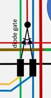
I made a diode gate - as noted by other above. Simple solution to the back feed voltage.
Blue, Green are the LH, RH indicator circuits to the LED's, the Red is the idiot light LED feed.
 

Attachments

  • Diode Gate.jpg
    Diode Gate.jpg
    8.1 KB · Views: 9
Top