Some interesting posts here which I may be able to add something to.
As already mentioned, when the points are closed, the heel of the cam is moving 'in free air' - it is not touching the cam ring. The points open when the fibre heel hits the rising edge of the cam. Whereabouts the heel hits the rising edge will depend on the size of the points gap. The size of the points gap is adjusted when the heel is on the top of the ramp. A small points gap will mean that the heel hits the ramp near the top. If the gap is increased, the heel will be hitting the ramp earlier. Changing the points gap changes the internal timing of the magneto - covered in more detail here: https://www.themagnetoguys.co.uk/points-gap
It's important to have the internal timing right - for all magnetos not just V twin versions. That's what the eccentric screw is for on the Lucas KVFs. A slot in the bottom of the cam ring fits over the eccentric screw so that, as the screw is turned, the cam rotates slightly thereby allowing the internal timing to be adjusted. In a fixed ignition magneto, the width of the slot in the cam ring is a clearance fit over the head of the screw. On manual ignition cam rings the width of the slot is much wider. The wider slot allows the cam ring to be rotated by the manual control to adjust the engine ignition timing. Unfortunately this also adjusts the internal timing of the magneto as mentioned earlier in this thread. One side of the wider slot is hard against the eccentric screw when the cam ring is in the fully advanced position, and against the other side of the slot in the fully retarded position. As before, the eccentric screw is adjusted to give best internal timing when the cam ring is in the fully advanced position.
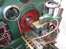
There was some discussion early on in this post about setting the internal timing to give the best spark at the retarded position. I tried to explain why this could not be done but seems there are some who cannot see that. There are a couple of things I can mention which reinforces what I was trying to say. The attached picture shows a Lucas K2F being tested on one of our test benches. The test bench allows us to control the speed of the magneto from zero to about 5,000 rpm. I think we are all agreed that a magneto finds it easier to produce sparks as the speed increases. That's why we are interesteed to see how slow the speed can go and yet still get a reliable spark. So we turn the speed right down until we see a missing spark. Then speed it up a fraction to get back to regular reliable sparks. This is all done with the magneto in the manually fully advanced position. If we now move the manual control to fully retarded, the sparks disappear - advance the ignition and they come back. When the manual control on these magnetos retards the ignition timing by rotating the cam ring, it also retards the internal timing of the magneto - that's why the sparks are lost. Testing documentation from Lucas states what the criteria needs to be for testing their magnetos. The part we are concerned with is the low speed test. Lucas states that the HT leads should be connected to independent 3 point test gaps set to 5.5mm. The lowest speeds at which a maximum of 5% missing sparks is noted is given as two figures - one when fully advanced, the other when fully retarded. On all the magneto types listed, the fully advanced speed is lower than the fully retarded speed. For the K2F, the figures are 150rpm advanced, 180rpm retarded. This, I believe, reinforces the idea that sparks are weaker when retarded, so much so that the speed of rotation needs to be increased to achieve acceptable performance. Yes, agreed, only 30rpm which, as a percentage, is not much. Interestingly, although the KVF magnetos we have been discussing were only provided with fixed ignition, they do none the less provide two figures. 150rpm (as with the K2F) when fully advanced, 250rpm when fully retarded. The fact that the KVF has one (internally) retarded spark even when fully (manually) advanced, is highlighted here by the need to run at 250rpm to get reliable sparks when retarded.
As already mentioned, when the points are closed, the heel of the cam is moving 'in free air' - it is not touching the cam ring. The points open when the fibre heel hits the rising edge of the cam. Whereabouts the heel hits the rising edge will depend on the size of the points gap. The size of the points gap is adjusted when the heel is on the top of the ramp. A small points gap will mean that the heel hits the ramp near the top. If the gap is increased, the heel will be hitting the ramp earlier. Changing the points gap changes the internal timing of the magneto - covered in more detail here: https://www.themagnetoguys.co.uk/points-gap
It's important to have the internal timing right - for all magnetos not just V twin versions. That's what the eccentric screw is for on the Lucas KVFs. A slot in the bottom of the cam ring fits over the eccentric screw so that, as the screw is turned, the cam rotates slightly thereby allowing the internal timing to be adjusted. In a fixed ignition magneto, the width of the slot in the cam ring is a clearance fit over the head of the screw. On manual ignition cam rings the width of the slot is much wider. The wider slot allows the cam ring to be rotated by the manual control to adjust the engine ignition timing. Unfortunately this also adjusts the internal timing of the magneto as mentioned earlier in this thread. One side of the wider slot is hard against the eccentric screw when the cam ring is in the fully advanced position, and against the other side of the slot in the fully retarded position. As before, the eccentric screw is adjusted to give best internal timing when the cam ring is in the fully advanced position.
There was some discussion early on in this post about setting the internal timing to give the best spark at the retarded position. I tried to explain why this could not be done but seems there are some who cannot see that. There are a couple of things I can mention which reinforces what I was trying to say. The attached picture shows a Lucas K2F being tested on one of our test benches. The test bench allows us to control the speed of the magneto from zero to about 5,000 rpm. I think we are all agreed that a magneto finds it easier to produce sparks as the speed increases. That's why we are interesteed to see how slow the speed can go and yet still get a reliable spark. So we turn the speed right down until we see a missing spark. Then speed it up a fraction to get back to regular reliable sparks. This is all done with the magneto in the manually fully advanced position. If we now move the manual control to fully retarded, the sparks disappear - advance the ignition and they come back. When the manual control on these magnetos retards the ignition timing by rotating the cam ring, it also retards the internal timing of the magneto - that's why the sparks are lost. Testing documentation from Lucas states what the criteria needs to be for testing their magnetos. The part we are concerned with is the low speed test. Lucas states that the HT leads should be connected to independent 3 point test gaps set to 5.5mm. The lowest speeds at which a maximum of 5% missing sparks is noted is given as two figures - one when fully advanced, the other when fully retarded. On all the magneto types listed, the fully advanced speed is lower than the fully retarded speed. For the K2F, the figures are 150rpm advanced, 180rpm retarded. This, I believe, reinforces the idea that sparks are weaker when retarded, so much so that the speed of rotation needs to be increased to achieve acceptable performance. Yes, agreed, only 30rpm which, as a percentage, is not much. Interestingly, although the KVF magnetos we have been discussing were only provided with fixed ignition, they do none the less provide two figures. 150rpm (as with the K2F) when fully advanced, 250rpm when fully retarded. The fact that the KVF has one (internally) retarded spark even when fully (manually) advanced, is highlighted here by the need to run at 250rpm to get reliable sparks when retarded.
Attachments
Last edited:
")