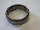
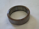
Hello Peter, Don't take too much off the cylinder registers, There is not a lot of alloy between the top of the cam spindle hole and the cylinder base, It could crack open, Cheers Bill.
You are using an out of date browser. It may not display this or other websites correctly.
You should upgrade or use an alternative browser.
You should upgrade or use an alternative browser.
Crank Case Inspection
- Thread starter Pushrod Twin
- Start date
I installed all of the spindles in one shot, however I was afforded the luxury of using Dan Smiths spindle setting kit which consists of one machined to length sleeve for each spindle. With hot cases and cold spindles (dry ice) it all went smoothly. The next day I used the slide hammer in the kit to move the spindles in or out a few thou to get a uniform line (no heat used for this) Ed Stevens book is the only publication to list a number for the postion of the spindle shoulders relative to the crankcase timing side face and it worked for me. Dan's jig put the spindles all very close to Ed Steven's suggested location. To set the final position of the spindles, I used a straight edge across the crankcase timing side faces, but spaced out on shim blocks at each end sufficiently to clear the shoulders by some amount, say .030. Then an .030 feeler gauge can be used to get all of the spindle shoulders sitting in plane with the cases and at the desired height. You will have to play with this a bit, but my particular set of components worked with the spindles set close in at thebottom of Ed Stevens range.the distance pieces then worked without extra shims, although one distance piece required shortenin by a few thou.
Hi there PT, are your spindle holes standard (worn) sizes or have you machined them oversize....?....Greg.
This appears to be one area of the cases which have not suffered too badly, the holes are all standard & tight!Hi there PT, are your spindle holes standard (worn) sizes or have you machined them oversize....?....Greg.
A bit late on this one. I would look at the inside of the timing cover where the discs go, compare the sizes of the orifice. If the existing holes are bigger than the ones in the discs, I'd reckon to fit them as you will get more oil to the big-end. Remember these are low pressure jobs. Roy.I see in TASL that ET234 oil restrictor discs are optional. How does one know if they are required? Run the engine with them fitted until something squeaks then remove them, or run without them watch for smoke??
Pushrod have you finished your project
I'm missing your posts
I'm missing your posts
Thanks Les, I didnt realise that I had such an adoring fan base!Pushrod have you finished your project
I'm missing your posts
There has been a little progress, it was interrupted by 4 days work across the ditch in Aussie. When I returned there was a box of parts from V3 in Melbourne, should have had them sent to WA & brought them home in my suit case but I wasnt that smart!
Am preparing to heat the cases & fit the spindles & bearings. Fitted the new oil pump into the cases, took a couple of evenings of fettling, cleaning scores out of the case bore & making a single point cutting tool to take a little high spot off the alloy bearing sleeve previously pictured.
Then I needed to reduce the timing side main bearing outer from 3/4" to 5/8", that was easy in the lathe with a carbide tool. I have no surface grinder & turning it was quicker anyway. Have also spent some time on other little distractions, talked to my favorite auto electrician re wiring which was followed by evenings spent buying electrical components. Also started into the crank. Can you believe looking at a crank with crappy old mains bearings full of coagulated 30 year old Castrol R that you would find a new Alpha big end bearing lurking inside? Sadly, as an indication of previous skilled workmanship, it was full of "fresh" 30 year old grease, some of which had separated the oil from the clay & the clay took some soaking & scrubbing to remove from the rollers & cages. Even better was the 2 rows of missing 3/16 x 3/16 rollers replaced with 3/16 x 1/4 rollers!
Which leads me to ask, I have another new BE, Alpha I think, with 3/16 rollers which fill the full length of the cage slots, is that common?


For anybody who may still be interested, here is the finished engine. I didn't feel the need to bore you all with a blow by blow account of the build, it is just another Vincent engine! There were some trials & tribulations, but I now consider it finished, halas, inshalla! The inlet stubs will need to be "adjusted" when the lump is settled in the Egli frame & I can judge accurately how much the rear Delorto clashes with the frame tube. The front needs a little massaging as well for clearance from the rear cylinder. Clutch & valve lifter cables were done as the build progressed, hence their appearance hanging off the back. The alternator is a 5 minute fit under the rear inlet stub. Now to finish the frame I started 20 years ago, see you all in Italy?


Can you believe looking at a crank with crappy old mains bearings full of coagulated 30 year old Castrol R that you would find a new Alpha big end bearing lurking inside?
YES!
Full marks, It's nice to see one get finished. If I may make a small comment, to my eyes the oil supply + return lines may have looked a bit neater if run behind the gearbox plate. Regards, Roy.
