Misc: Everything Else 1951 Black Shadow Restoration

Martyn Goodwin

Well Known and Active Forum User
Non-VOC Member
Martyn is correct in saying that torque figures are not given in the First Edition of KTB, but they are given in the Second Edition, on page 161 as 30 lb.ft. and 40 lb.ft. respectively, and it states that those figures are taken from the Works Instruction Sheets.
Hi Peter,

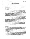
I have 2 editions of the works sheets One is dated May 1953 - part of it is in the attached jpg. The other is a 'update' by Griffin dated August 1998 - and part of that is the pdf attachment.

BOTH specify that the nuts are to be tightened to 30 ft/lb.

Remember as the motor warms up that the muff will expand upwards at TWICE the expansion/growth rate of the steel studs and that will increase the effective loading on the nuts and studs. Having studs pull out of the cases is a very expensive repair job.

But then again its not my motor.

Martyn
 

Attachments

  • IS 12 1953  001.jpg
    IS 12 1953 001.jpg
    338 KB · Views: 10
  • IS 12 1998 001.pdf
    561.8 KB · Views: 7

Peter Holmes

Well Known and Active Forum User
VOC Member
Martyn
I was not suggesting that I thought 40 lb.ft. was the correct torque figure, only corroborating that the figures Craig quoted were in fact taken from K.T.B., and that E.M.G.S. stated that the figures quoted came from the works instruction sheets. I have no idea what figures I am using as last time mine were bolted down they were done by feel, I do own a bloody great big Williams torque wrench, but it has not been calibrated in 50 years and I am not sure that I would trust it, it is the snap out type using a cam adjustable spring loaded pressure, all seems a little crude to me, can you now get them with a more accurate method of adjustment.
 

Martyn Goodwin

Well Known and Active Forum User
Non-VOC Member
Martyn
I was not suggesting that I thought 40 lb.ft. was the correct torque figure, only corroborating that the figures Craig quoted were in fact taken from K.T.B., and that E.M.G.S. stated that the figures quoted came from the works instruction sheets. I have no idea what figures I am using as last time mine were bolted down they were done by feel, I do own a bloody great big Williams torque wrench, but it has not been calibrated in 50 years and I am not sure that I would trust it, it is the snap out type using a cam adjustable spring loaded pressure, all seems a little crude to me, can you now get them with a more accurate method of adjustment.
Hi Peter,

No criticism intended. Just passing on a bit of historical information I have access to.

There is a swag of contradictory information in this world.

And I share your jaundiced view of some old measuring tools - modern replacements are often cheap as chips

regards

Martyn
 

Peter Holmes

Well Known and Active Forum User
VOC Member
So the only conclusion that I can draw is that someone along the way made a typing error, or Phil Irving got it wrong. I never had the pleasure of meeting Phil, but had I, I cannot imagine myself being anyway near brave enough to suggest to him that he got it wrong, it would give me nightmares just to consider it.
 

greg brillus

Well Known and Active Forum User
VOC Member
My first question to this is........what if any prep was done to see that the head to liner joint is correct.........most are not........this leads to leaks, the next course of action is to pull the heads down even more........I had a barrel/head combo recently that was assembled with loads of what looked like loctite 518 or similar...... I had to heat the joint with a blow torch, then drive the 2 apart with a sharp wood chisel to separate them..........don't panic, very little if any damage was done........and yes I did try a large block of hardwood down the bore with blows from a hammer to no effect........Plenty of engines out there who's head nuts are torqued way too much.........This generally will result in the lower stud threads in the crank case failing........The thought being that if you tighten them more, then you don't need to re torque them later........Well I guess we all like to think of our bikes as being the ultimate classic bike........Bit like the "Titanic" and we all know what happened to that.......The fine alloy threads in these crank cases do in fact have an "elastic limit".........Race or road engines........Low or high compression.......no matter........30 to 32 Ft Lb's is all you need.
 

craig

Well Known and Active Forum User
VOC Member
Making some progress with clutch side as I await parts for timing.
Spent quite bit of time adjusting the exhaust lift linkage.

20210907_ShadowCyl9.jpg
 

craig

Well Known and Active Forum User
VOC Member
Spent time today checking push rod lengths, adjuster clearance to caps, timing cams to crank, adjuster types (allen, hex, slotted), etc.

Fitted Amal premiers to manifolds, manifold to rear requires machining as usual to correct an angle mount issue.

20210912_CamTime554X11.jpg


Here is a tool to check adjuster clearance when needed.
Cut open a cap.

20210912_AdjClearanceCk1.jpg
 
Last edited:

Martyn Goodwin

Well Known and Active Forum User
Non-VOC Member
Spent time today checking push rod lengths, adjuster clearance to caps, timing cams to crank, adjuster types (allen, hex, slotted), etc.

Fitted Amal premiers to manifolds, manifold to rear requires machining as usual to correct an angle mount issue.

View attachment 44760

Here is a tool to check adjuster clearance when needed.
Cut open a cap.

View attachment 44761
Manifold issues - where did you get the manifolds from? I found that these work a treat!
 

Attachments

  • AMAL Manifolds.pdf
    168.2 KB · Views: 41

craig

Well Known and Active Forum User
VOC Member
Bought a set of those years ago, tried them now, the rear does not allow Battery and Amal in same space.
Mount flange is not flat as well.

Maybe you are supposed to machine the flange and move the twin battery?


20210913_RearAmalManifold1.jpg
 
Last edited:
Top