During the break, I set about to rewire the 47 Rapide and in the process update to modern standards - including adding LED running lights, LED turn signals, LED tail light and LED idiot dash lights. I was also wiring in a new electronic POWER ARC ignition and needed a key switch. Also needed was a small discrete handlebar switch with horn, turn and high beam function - there are plenty available to choose from, but the gauge of wire they use is not suitable for the high output for headlight and horn, which means that relays need to be used.
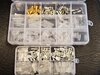
Amazon is where I was able to source everything needed included wire connections (bullet/spade), the automotive relays, handlebar switch, ignition switch, spools of 18ga coloured wire, shrink wrap sleeving, bundles of coloured LED's, etc. The turn signals are miniature bullet units sourced from a motorcycle cafe parts supplier.
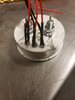
Wiring the McDougalator also became a challenge due to lack of information. In the end I was able to use the Ignition light option that comes with the rectifier unit, although to adapt it to a LED idiot light I had to install a 50W load resistor to simulate the 34W bulb..
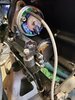
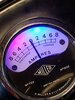
My headlight is a 8" Miller repo with the white backed ammeter. My ammeter had suffered damage and needed to be JB welded back together - I took the opportunity to drill the back and install three coloured LED idiot lights. These LED's come pre-wired for 12V and include their own resistor - pennies on Amazon for bundles of 10 in 5 colours. The LED turn signal dash idiot light required a diode gate.
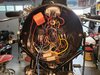
The large 8" headlight shell proved roomy enough for the 2 automotive relays and the flasher unit. They were secured with adhesive velcro tabs to the shell.
I decided I needed a plan to follow and found little information on wiring Vincent's this way. I prepared a full colour wiring diagram on the computer and printed in colour, mounted on foam board and set about the wiring. It took about 3 weeks of 2-4hours every other day. Working methodically, one circuit at a time.
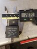
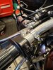
I am very disciplined about the wiring methods - all connectors are crimped, soldered, shrink wrapped at the joint and covered with a vinyl sleeve. Wires are sheathed. Getting three 18ga wires up each of the rear fender stays proved easy in the end and provided for the turn signal, tail light, running lights, stop light.
The new wiring has proved itself - the bright turn signals are amazing, bright tail light and the running lights ensure you can be seen. Done discretly, the wiring does not look much different than a stock bike and the turn signals are the only outward sign that anything is different.
Amazon is where I was able to source everything needed included wire connections (bullet/spade), the automotive relays, handlebar switch, ignition switch, spools of 18ga coloured wire, shrink wrap sleeving, bundles of coloured LED's, etc. The turn signals are miniature bullet units sourced from a motorcycle cafe parts supplier.
Wiring the McDougalator also became a challenge due to lack of information. In the end I was able to use the Ignition light option that comes with the rectifier unit, although to adapt it to a LED idiot light I had to install a 50W load resistor to simulate the 34W bulb..
My headlight is a 8" Miller repo with the white backed ammeter. My ammeter had suffered damage and needed to be JB welded back together - I took the opportunity to drill the back and install three coloured LED idiot lights. These LED's come pre-wired for 12V and include their own resistor - pennies on Amazon for bundles of 10 in 5 colours. The LED turn signal dash idiot light required a diode gate.
The large 8" headlight shell proved roomy enough for the 2 automotive relays and the flasher unit. They were secured with adhesive velcro tabs to the shell.
I decided I needed a plan to follow and found little information on wiring Vincent's this way. I prepared a full colour wiring diagram on the computer and printed in colour, mounted on foam board and set about the wiring. It took about 3 weeks of 2-4hours every other day. Working methodically, one circuit at a time.
I am very disciplined about the wiring methods - all connectors are crimped, soldered, shrink wrapped at the joint and covered with a vinyl sleeve. Wires are sheathed. Getting three 18ga wires up each of the rear fender stays proved easy in the end and provided for the turn signal, tail light, running lights, stop light.
The new wiring has proved itself - the bright turn signals are amazing, bright tail light and the running lights ensure you can be seen. Done discretly, the wiring does not look much different than a stock bike and the turn signals are the only outward sign that anything is different.