What a fabulous report on the fitting of the Kawasaki discs along with great photos. My everlasting thanks as I will now be able to at least forward the article to anyone interested. As noted, the MPH surely had to be designed to carry in-depth articles such as this one and I'll just be real disappointed if it does not appear in its entirety in the publication. Years back when I did this conversion the twin leading shoe arrangements now on the market were not available. And as I recall Ian Savage was traveling along the road when he found himself (and lady passenger) in a 'must stop now' situation. I believe Ian told me he was able to 'dive' either left or right and managed to stop about one and a half car lengths past where he wanted to. In other words, if he had not been able to dive left or right he would have surely plowed into the back of the vehicle in front of him, and that's when he decided to put discs on. It goes without saying I am in total agreement and for those who are so concerned with originality out there, please consider that if Phil Irving had still been with the company and he had seen discs on a few of the race cars of the day, Mercedes comes to mind, he would have put discs on the Vin. A motorcycle has 75% of its stopping power on the front wheel and I worked on my original brakes and cloned the famed magazine article of the early Fifties that displayed the stopping power of the Vincent. You can potter along and say "Oh, I'm just out for a little ride," until that day you experience an Ian Savage situation and your thoughts of originality will be long gone. Master machinist Roy Cross, who spent a virtual life-time studying the Vin and its mechanics recommended to me that I install discs rather than fooling around with the stock brakes any longer, and I took the advice. Best mod I've ever made. Plus, you can put the stock brakes back on in minutes.A Disc Brake Conversion for a Vincent with Girdraulic Forks
The text below was written by Ian Savage. As noted in the first paragraph, Brian Chapman did the initial design and research to find suitable existing and fairly readily available components that could be used in the conversion. Two Coventry section members have fitted this conversion. I fitted it to my Rapide and Rob Smart to a "D" sidecar outfit. My own additional notes that I made based on my own experience of doing the conversion are to be found at the end of this post.
I have made some drawings based on Ian’s original sketches mentioned in the text and included some photographs of my conversion. Regarding the drawings, I am not a draughtsman but hopefully they will suffice and make the process easier to follow. Eddy.
Twin Disc Set Up
Introduction
This set up designed by Brian Chapman, has to my knowledge been owner fabricated and fitted to 3 twins, 1 outfit plus a single disc set up on Comet.
It is based on a Kawasaki Zephyr 550 or 750, front brake set, 300mm discs, callipers and master cylinder. Kawasaki uses the same parts on many bikes in their range a list of possible matches is attached based on EBC replacement disc and pad part numbers, you need to check to be sure.
What follows is a description of how I made and fitted the set up and although it is based on Brian's design but not necessarily identical to it.
Disclaimer
Messing with brakes is dangerous, if you use any of the attached information it is entirely down to you, if it does not work, something gets damaged or you have an accident don't come crying back to Brian or I.
What follows is not necessarily fully complete and you must check all items and
operations for accuracy and safety.
No warranty or design liability is expressed or implied. (I recommend you read this again and fully take on board the message. Ed)
Discs
The first thing to consider is that the inside diameter is 0.1" larger than the o/d of the hub, if you have access to a large enough machine tool to be able to make and shrink in an aluminium ring and then machine back, this would be the best method. For the non-speedo side, you could make the Cover Plate in Sketch 1 (Drawing 1 Ed) from thicker material and machine the spacer ring as part of that. I used some 25 thou brass strip to make two packing rings soft soldered together to fill this space.
The disc already has 5 fixing holes but on the wrong p.c.d. for the Vincent hub so it is necessary to drill new holes in between the existing. If you have access to a machine with a dividing head then this would be the best method, I used a pillar drill and a spoke flange as a guide. The holes are very close to breaking through in to the i.d. of the disc centre so this needs to be done after the spacer is fitted and carefully.
Disc Mounting
On the non-speedo side this is straight forward all that is required is a Cover Plate to hide the now redundant mounting holes, made as per attached sketch 1. 1 (Drawing 1 Ed)
On the speedo side however, to enable the speedo drive to be retained the speedo ring needs to mounted further back on the bearing housing of the hub. To do this machine out the speedo ring gear a few thou' less than the o/d of the housing. You now need to find suitable material for the speedo drive inner cover, both Brian and I raided the pots and pan cupboard Brian found a S/S lid I used an aluminium pan base from an old camping set. The thinner this item is the better as clearance in the speedo drive area is tight, due to this there is no room for a Cover Plate as above so use washers under the heads of the hub bolts.
The important thing is the i.d. of the drive cover must be no less than 5.85" (148mm) as per sketch 2 1 (Drawing 2 Ed) to clear the speedo drive gears and the o.d. no greater than 6.2" (158mm) as this is the maximum diameter the outer cover can be.
Once a suitable item is found it will need to have a large centre hole cut to fit over the hub and have the 5 mounting holes drilled, and then the cover needs to be 'dished' to the same profile as the disc carrier. Leave the height of the cover edge oversize, as this dimension can only be determined after the outer cover and Calliper Carrier are made.
Don't fit the speedo ring gear or the inner cover yet as fitting this, and the final cut to the inner cover edge are almost the last operations.
Calliper Carriers
Two identical but handed Calliper Carrier plates need to be made as per sketch 3 (Drawing 3. Ed) the depth of the recess is greater than necessary to allow for shimming to enable wheel entralisation and calliper clearance.
Speedo G/Box Carrier Plate
This can be made as per sketch 4 (Drawing 4 Ed) but the groove in the back needs to mate up with the dimensions of your inner cover.
Now the Speedo G/Box will clash with the front mudguard stay, you can get round this in a number of ways,
1) Move the position of the g/box round from the 2 o'clock to the 4 o'clock position and use a longer cable to flex around the stay (Brian's method).
2) Leave g/box in the standard place and bend the stay round it (my method).
3) Get a 'Series D' type long shaft g/box (or get a Series 'D'!).
In your chosen position fit the Speedo G/Box Carrier Plate to the Calliper Carrier Plate with countersunk screws. Remove a calliper bracket from one of the callipers and offer up to make sure there is no clash, if there is turn or file a little off the Speedo G/Box Carrier Plate until clear.
Fixing bolts
I made my own up from s/s whit hex bar as per sketch 5 (Drawing 5 Ed) you can use commercial items but remember the calliper bracket is pre-threaded metric so you will need to carry metric spanner to suit any bolt you fit.
Wheel Assembly
Fit the hollow axle and bearings and shim up as normal, fit both discs (use 3 bolts with plain nuts in the speedo side as it will have to come off again), check the 'end of hollow axle to disc face' distance and equalise by moving shims from side to side. Fit the calliper brackets to the Calliper Carrier Plates and fit on hollow axle this will probably touch the disc face if so add shims between the Calliper Carrier Plate and the bearing until you have at least 25 thou' clearance between them (make sure the small brake pad clips are fitted).
Now you can work out how much depth is needed on the speedo drive inner cover by dead measurement, and you can cut it to suit. Take speedo side apart then re-assemble with the speedo drive inner cover and re-check. Once you are satisfied all is fitting well, you can finally reassemble with the correct hub bolts and nylock nuts, press on the speedo ring gear.
Mounting into the Forks
Loosely fit carrier to the wheel into the forks, you may need to relieve the Calliper Carrier Plates to clear the bottoms of the spring boxes, line up the Calliper Carrier Plates with the brake anchor point on the forks and measure the distance between them and make spacers to suit, as Sketch 5. (Drawing 5 Ed)
The rear mudguard stay need to be made to clear the calliper so put a small bend in to give a nice line and a spacer to hold it off the fork blade, (remember the calliper will move out as the pad wears so allow for this). The front will need a set or not depending on what you decided above.
Adjust the speedo g/box to suit the depth to get a good mesh on the ring gear.
Hydraulics
The master cylinder can be from any make or model you fancy to suit your taste, if you need a mounting for a mirror etc. The important thing to note is the piston size, cast or stamped into the body, it will be either a fraction 1/2”, 5/8, or a number 14 this is the piston diameter in inches or mm. Now this is where Brian and I differ. The Zephyr master cylinder I received from the breakers was a 14, Brian however has settled on a 5/8. I've ridden Brian's bike (although not in anger!) and found little difference in the feel, Brian's master cylinder is Yamaha (5/8), mine Honda (14) just because I preferred the look of it.
To get the one master cylinder to feed two callipers you will need a Splitter the one off the Zephyr is ok but it does not fit between the fork blades behind the bridge plate, you may find one at your breakers that does, or you can make one as I did see sketch 6 (Drawing 6. Ed). Get new lines made-up by a bike shop or through a catalogue, I used MAP s/s braided, s/s fittings and black shrink-wrapped. You will need to specify the length and end fittings (mine was l x 450mm 2x 400mm and 'Zephyr' fittings). If you have a different master cylinder or splitter type or position your lines may be different. Use new DOT4 fluid, flush through well and fit new pads.
Last thoughts
All the work was done at home with hand tools, a pillar drill and a Myford 3¼” lathe, except machining the recess in the Calliper Carrier Plate were you would need a mill or larger lathe and the welding of the splitter.
I've not mentioned anything about finish (painting etc) I'll leave this to you to carry out to your preference at the appropriate time in the assembly process.
Well I can't think of any more, Brian's had a look at this and he can't either. Good Luck. Ian Savage
ZR250 91-95
ZZR 250 90-01
ZXR 250 89-01
ZRX 400 94-01
ZR 550 Zephyr 91-99
ZZR 600 90-02
ZX6-R 95-97
EJ 650(E650) 00-02
ZR 750 Zephyr 92-
GPZ 900 90-96
ZG 1000 94-00
GPZ 1100 95-98
EBC Replacement MD4008
Calliper Fitment List (note, based on EBC Pad type FA 129)
ZR 250 91-95, ZZR 250 90-01, GPZ 500 87-01, ZR 550 Zephyr 91-99, ZL 600 95-97, ZX6-R 95-97, ZR 750 Zephyr 92-95, GTR1000 94-99 + some later models.
Drawings
View attachment 48463
View attachment 48464
View attachment 48465
View attachment 48466
View attachment 48502
View attachment 48468
View attachment 48469
View attachment 48470
Photographs
View attachment 48472
View attachment 48474
View attachment 48475
View attachment 48476
View attachment 48477
View attachment 48478
View attachment 48479
View attachment 48480
View attachment 48481
View attachment 48482
View attachment 48483
View attachment 48491
View attachment 48492
View attachment 48493
My Additional Disc Conversion Notes
I recommend you do lots of measuring to check sizes and clearances before you dive in and start machining.
I couldn’t find a suggested pan lid/saucepan to modify to make the speedo drive inner cover, so I fabricated a cone from sheet metal.
I have included a drawing of the development for the conical part. I suggest that it might be a good idea to make one out of some thin card first and see how well this fits the aluminium disc carrier. The CAD drawing shows a section at one end without hatching that can be used as an overlap to glue a cardboard cone.
The base can be made using the diameters and hole pattern the same as the disc cover plate drawing.
The only metal I had to hand at the time was the side of an old computer case. (It was only 1mm/0.040” thick, easy to form but more difficult to weld. (Depending on your sheet metal working skills 18 gauge/ 0.048” might be a better compromise and easier to weld.)
The straight portion welded to the outer end of the cone fits into the groove of the speedo gearbox mounting plate to deter water ingress to the speedo gears. I suggest that it might be an idea to make this a little on the wide side and then trim it to size after a trial assembly to get the best depth fit into the groove. If it is too short, then you will have some annoying correction work to do. (Guess how I know this!)
Some installation dimensions may differ a little due to some components differing a little in size. The speedo cover plate drawing show 0.187 thickness for the plate. In hindsight, I would have used thicker material to give more leeway for machining the depth of the rebate for the cone of the inner cover. (It is easier to machine it thinner afterwards if needed than to find it too thin to make the rebate deep enough.)
Longer H19 hub bolts may be needed to take account of the thickness of the disc cover plate, etc. Refitting the hub bolts and nuts is an extremely tedious process. I just fitted three bolts to line things up during trial assemblies to check things. Access to the hub area between the spokes is limited and it is quite difficult when the discs are fitted. When I had a new rim fitted I had to repeat the tedious process of removing the H19 bolts and refitting them. (It might help if you have very small hands or fingers 6 inches long.) In hindsight it would have been far quicker and easier to use cap head Allen bolts with Nylock nuts so a spanner could hold the nut between the spokes and the bolts tightened from outside with an Allen key.)
To ensure that your speedometer cable still fits it is probably best to best to do a trial assembly with the speedometer cable connected at both ends and then spot through to the right-hand calliper mounting plate and the speedometer gearbox carrier plate with a small drill. You can just do one hole and then disassemble and complete the operation off the bike. (When I first did this, I turned the speedometer mounting plate to where I thought the speedometer gearbox should be but didn’t have the cable connected. When I tried the cable, it was ½” short so I had to drill and tap two new holes to mount the speedometer gearbox mounting a little more anti-clockwise on the plate.)
The lower mudguard stays foul the callipers. As a temporary measure, I used a longer bolt with a spacer for the fixing at the bottom of the Girdraulic fork legs. (I have since made a new longer lower mudguard stay that sweeps under the calliper.
I didn't make the Coupler/Splitter as I already had two separate hoses long enough to run directly from the master cylinder to the callipers. I now have a coupler that I can use to run a single hose from the master cylinder to reduce the clutter at the handlebars. I’ll do that when I’ve got some hoses of a suitable length.
Check carefully that the top link of your front forks does not hit the master cylinder or hose fittings on full bump. Depending on what make of master cylinder you use you may have to move the master cylinder outboard along the standard low handlebar to make everything miss. With the master cylinder that I used, I pivoted the FF11 handlebar clip backwards a little to create a bit more clearance. (Having two hoses to the master cylinder made this more difficult.) If you have higher bars fitted, you probably won’t have a problem.
The calliper carrier plate needs relieving where it abuts the FF16AS Inner Spring Case. A hatched area is shown on Drawing 3 to indicate the relieved area. There is no dimension given for this. Do a trial assembly and mark the plate area to be relieved with a felt pen to give you a guide. You may do this by hand with a round file or a milling machine if you have that luxury. I used a handheld rotary cutter. Check that when the FF17 Spring Case Pivot bolts are fitted that the end of the bolt doesn’t protrude and touch the carrier plate and that the bolts fixing the calliper to the plate don’t foul the disc. I drilled and wired these bolts. On a trial assembly check the dimension between the calliper plate and the bottom of the fork leg and make the thickness of the torque bolt spacer to suit.
Weight wheel with aluminium rim, tyre, and original brakes complete = approximately 35lbs.
Weight of my wheel with aluminium rim, tyre, discs, and callipers = approximately 28 lbs.
Why did I do this conversion?
The first build of this Rapide had quite good brakes with finned Shadow drums and some green linings. When these needed replacing, I was unimpressed with the stopping power. Riding in today’s traffic needs good brakes as all modern vehicles have good brakes so you need good brakes especially so when carrying my wife on the back seat. I looked at the options and two leading shoe conversions or the 8” front brake from the Spares Co were over £1000 at the time. I like to try and do things for myself, so I thought I’d have a go. I had to buy material for the calliper mounting plates but had material to hand to make the speedo drive plate. I made a good buy on eBay and got a Kawasaki wheel complete with discs and master cylinder, hoses and callipers from the same seller. It cost me probably less than £150 in total not counting one or two sundries that I already had. The disc brakes work really well and although I am not an originality person I could just refit the original parts if I wanted to.
If I think of anything else, I’ll add it here later.
Eddy Grew.
You are using an out of date browser. It may not display this or other websites correctly.
You should upgrade or use an alternative browser.
You should upgrade or use an alternative browser.
H: Hubs, Wheels and Tyres Disc Brake Conversion with Girdraulics and Kawasaki Parts.
- Thread starter BigEd
- Start date
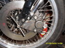
I started a conversion in lockdown and have everything done ready now other than the hoses (these pictures are half way along), I just haven't got round to fitting everything (still on the Shadow drums/alloy brakeplates) these are Honda Superdream discs with Lockheed alloy calipers, when complete I will have about £300 in it, a vast difference between this and the cost of any of the TLS set ups.
Attachments
I am not up to date with current vernacular and don't know what OT stands for. My point is that by 1954 the disc brake itself was no longer a theory but a reality. If we look back at Irving's career we see he was the first to install the airplane style shock absorber, on the Velo I believe. If the Stevenage factory would have had the financial and technical means my speculation is the Vincent would have been the first motorcycle to sport disc brakes, at least in front. We recall Detroit's intro of disc brakes were seen on the front of the vehicles.
To me, when working on my Vincent cost means approximately nothing. I buy the best, try to hire the best and later on I've forgotten all about the cost if the modification/fix works. I am SO surprised that no article in the MPH has yet to cover just how to install discs on (at least) the Series C.
,I started a conversion in lockdown and have everything done ready now other than the hoses (these pictures are half way along), I just haven't got round to fitting everything (still on the Shadow drums/alloy brakeplates) these are Honda Superdream discs with Lockheed alloy calipers, when complete I will have about £300 in it, a vast difference between this and the cost of any of the TLS set ups.
A couple of months ago I had a court case settled in my favour after a young woman pulled out in front of me while I was riding my Rapide. Because I had the discs fitted I was able to stop before I hit the side of her car. The bike was damaged a little as it went down on its side as I skidded to a halt and my injuries were not major. I went to court as she denied she had pulled out in front of me! It was 2 years coming to court as the Covid epidemic intervened and everything was delayed. If I had not had the excellent braking power of the discs I think that the Rapide would likely have been very badly damaged or written off and I may not even have still been here to write this post. Function better than form is my preference.What a fabulous report on the fitting of the Kawasaki discs along with great photos. My everlasting thanks as I will now be able to at least forward the article to anyone interested. As noted, the MPH surely had to be designed to carry in-depth articles such as this one and I'll just be real disappointed if it does not appear in its entirety in the publication. Years back when I did this conversion the twin leading shoe arrangements now on the market were not available. And as I recall Ian Savage was traveling along the road when he found himself (and lady passenger) in a 'must stop now' situation. I believe Ian told me he was able to 'dive' either left or right and managed to stop about one and a half car lengths past where he wanted to. In other words, if he had not been able to dive left or right he would have surely plowed into the back of the vehicle in front of him, and that's when he decided to put discs on. It goes without saying I am in total agreement and for those who are so concerned with originality out there, please consider that if Phil Irving had still been with the company and he had seen discs on a few of the race cars of the day, Mercedes comes to mind, he would have put discs on the Vin. A motorcycle has 75% of its stopping power on the front wheel and I worked on my original brakes and cloned the famed magazine article of the early Fifties that displayed the stopping power of the Vincent. You can potter along and say "Oh, I'm just out for a little ride," until that day you experience an Ian Savage situation and your thoughts of originality will be long gone. Master machinist Roy Cross, who spent a virtual life-time studying the Vin and its mechanics recommended to me that I install discs rather than fooling around with the stock brakes any longer, and I took the advice. Best mod I've ever made. Plus, you can put the stock brakes back on in minutes.
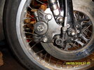
Do you plan for sheet metal enclosures for the speedo gear, similar to Ian's approach? Also, the new bolt holes must be just as close to the bore of the disc carrier.I started a conversion in lockdown and have everything done ready now other than the hoses (these pictures are half way along), I just haven't got round to fitting everything (still on the Shadow drums/alloy brakeplates) these are Honda Superdream discs with Lockheed alloy calipers, when complete I will have about £300 in it, a vast difference between this and the cost of any of the TLS set ups.
This tells us you're a rider, out there among 'em as I consider myself. I haven't yet been able to make my front wheel skid as I used to be able to do with a disc-braked Harley Super Glide but I could not be happier than hearing of Ian Savage's experiences and obtaining the plans for the Kawasaki based discs. My only complaint is that I haven't been able to replace the top cover on my Yamaha master cylinder and I've been promised a Vincent one for several years now.A couple of months ago I had a court case settled in my favour after a young woman pulled out in front of me while I was riding my Rapide. Because I had the discs fitted I was able to stop before I hit the side of her car. The bike was damaged a little as it went down on its side as I skidded to a halt and my injuries were not major. I went to court as she denied she had pulled out in front of me! It was 2 years coming to court as the Covid epidemic intervened and everything was delayed. If I had not had the excellent braking power of the discs I think that the Rapide would likely have been very badly damaged or written off and I may not even have still been here to write this post. Function better than form is my preference.
I have locked the front end of my Rapide on a dry day "showing off" my Speet brakes.
Note to self, Robert, don't do that again!
Note to self, Robert, don't do that again!
I have fitted the dust enclosures. To make space for the calipers the LH disc required a 5mm spacer, however on the RH side this brought the disc spokes into contact with the speedo drive gear, my solution was to turn most of the braking path off one disc and the centre out of another and rivet them together (ie moving the centre of the disc back 5mm) using stainless rivets.Do you plan for sheet metal enclosures for the speedo gear, similar to Ian's approach? Also, the new bolt holes must be just as close to the bore of the disc carrier.
Last edited: