You are using an out of date browser. It may not display this or other websites correctly.
You should upgrade or use an alternative browser.
You should upgrade or use an alternative browser.
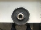
E: Engine Cams- looking end on
- Thread starter vibrac
- Start date
Looks like it has had a stellite weld repair, maybe a Gary Robinson job, I know Gary retired, and I am hopeful that he is still with us, perhaps he could identify your cams, he must have repaired a huge amount in his time, if he can't identify them, I doubt that anyone can.
Somewhere else in this massive forum, I'm sure someone posted pictures of cam profiles in the form of graphs. ( or was it in MPH ? ) My son had a choice of cams for his comet and made profiles by turning them 5 deg at a time in the lathe with a timing disc on, recording it all on something called a spreadsheet. Beyond me......
That seems to me to be the only certain way ?
That seems to me to be the only certain way ?
They are not all re-welded take no 6 for example (below) its symmetrical profile suggests a milder cam than No10 but if it is, is it a 1 or a 3?
I could certainly produce graphs as you suggest directly from the cam but how that relates to the lift profile in an engine is another subject

I could certainly produce graphs as you suggest directly from the cam but how that relates to the lift profile in an engine is another subject
As the cam rotates the contact line between the cam and follower slides up and down the follower and changes the ratio between the cam eccentricity and the valve lift. I have many times put valve lift graphs on here but you can't compare those with cam eccentricity figures For example, I can tell just by looking at Vibrac's picture in #3 above that the upper cam lobe is more like a Mk II than a Mk I but what it really is cannot be determined just by looking. It, preferably the valve lift, needs to be measured to determine whether it is usable or whether it would wreck an engine. If you have cams which have been used in one of our engines and which are known not to be destructive then just looking will tell you whether it is a Mk I or a Mk II. You will never see the difference between a Mk I and a Mk III and of several cams I have measured I have never seen quieting ramps.
Looking at the photos, the cams are in the same relative position. The right side of the photo is TDC where you adjust the tappets. The lobes are a bit biased to the left side of the photo, so that would be the overlap side of the cams. The overlap is a little more difficult to see, but if you remember that the pushrods are separated by a reasonable distance you will see that both pushrods are sitting on the lobe ramps and slightly open. This is also where equal lift occurs. On the right side, no lift occurs.
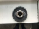
The lobes on the number 10 cans are fatter than the number 6 lobes, which means the valves will be open longer, particularly when they are open. This longer duration normally occurs on a race cam, which should be the Mk2.
The number 6 cam lobes are more pyramidal showing less duration and height (or valve lift) than a race cam. The number 6 cam should be a Mk1 or Mk3.
The Mk1 and Mk3 should be the same cam. The Mk3 is a Mk1 with quieting ramps. I think what this means is that the Factory made the lobes slightly more "arced" than "flat," but as Norman says, it is difficult to find the "quieting ramps,"
It is worth measuring the base circle of the cam. An old "hot rodding" trick is to reduce the diameter of the base circle (on the right side) giving the lobes a bit more opening relative to the closed valve. It is good to find that out sooner than later.
David
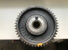
I can do digital measurements of new genuine Andrews Mk 2 cams. In fact I got them somewhere when I copied one set, Norman got one of them still. Basically lift numbers should be available to identify Mk1 or Mk2 . In Vibrac´s photo type C 6 cannot possibly be a correct grind as it appears to be near symmetric. We are dealing with cam follower levers so in these types you NEVER can have symmetric cams for achieving symmetric valve lift curves: The contact point between follower and cam moves away or towards the lever pivot and lever ratio changes while doing so. So that is why correct Vincent cams got that very particular cam shape with some pointy place in consequence from the non-curved follower but dead flat lever. Was not the best idea leading to the pointy cam shape and a problem for oil film there.
In my photo the new Andrews Mk2 below.
Vic


measuring cams:

copied cams:

In my photo the new Andrews Mk2 below.
Vic
measuring cams:
copied cams: