David Bowen: Fishers Green

davidd

Well Known and Active Forum User
VOC Member
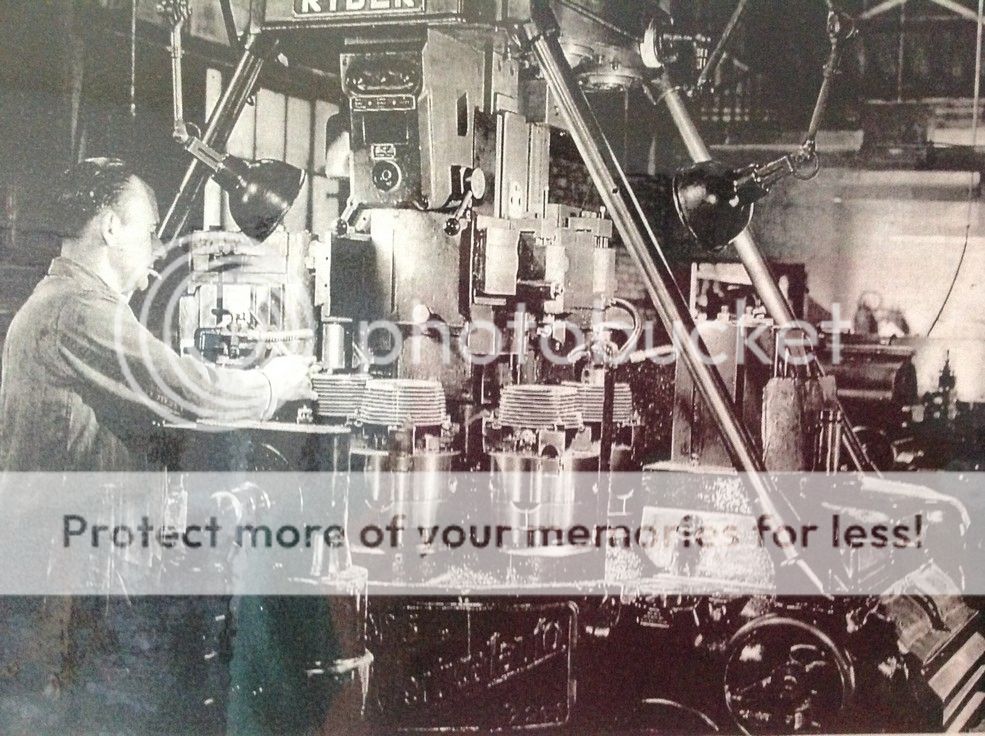
Vincent number 2 Factory (Fishers Green.) George Barber at his work station with the Ryder. George was setter and operator. He raced a Series A TTR pre-war and
at Brooklands. His son still lives in the Stevenage Area and still has one ofGeorges Series A's.


David
 

ogrilp400

Well Known and Active Forum User
Non-VOC Member
G'day David,
As a fitter and machinist these photos interest me intensely and gives insight into how the operations were carried out. Obviously the Ryder machines the cylinders but I'm trying to work out how the cylinders are held. It looks like they are being held by the top fin but surely this would not be sufficiently rigid to carry out machining of the sleeve bore and the stud holes and facing off of the cylinder base.

Phelps.
 

ogrilp400

Well Known and Active Forum User
Non-VOC Member
Also a machine like this must have been incredible expensive especially so for a small firm like Vincent's. I wounder if these machines were obtained under subsidy during the war for the war effort.

Phelps.
 

clevtrev

Well Known and Active Forum User
VOC Member
G'day David,
As a fitter and machinist these photos interest me intensely and gives insight into how the operations were carried out. Obviously the Ryder machines the cylinders but I'm trying to work out how the cylinders are held. It looks like they are being held by the top fin but surely this would not be sufficiently rigid to carry out machining of the sleeve bore and the stud holes and facing off of the cylinder base.

Phelps.
If you go to the image on the website that David has given, open up the work folder, right click on the image and select `copy image`. Open Accessories, then Paint, paste, and you will have a very good resolution picture, that shows the muffs being clamped down on the top fin.
 

clevtrev

Well Known and Active Forum User
VOC Member
Ryder1.jpg
This might help.
 

bmetcalf

Well Known and Active Forum User
VOC Member
I guess it must not be in bending, so not too bad. Were they individually leveled to account for fin thickness variations?
 

jim burgess

Well Known and Active Forum User
VOC Member
If you go to the image on the website that David has given, open up the work folder, right click on the image and select `copy image`. Open Accessories, then Paint, paste, and you will have a very good resolution picture, that shows the muffs being clamped down on the top fin.
I just did all that and amazingly works as specified! More to the point I think you are right! How on earth did they keep it all square? Judging by the cylinder muffs I have seen most bores I have to be out of square..
Jim Burgess Norvin S.O.
 
Top