When you assemble an engine on the bench you could save you a lot of time that day and later as well when you provide marks on cam gears corresponding to marks on the engine case at that same time. Best idea is to have extra light valve springs there and two clocks sitting on the valve stem end by having old caps with 8mm adapters for (digital?) clocks - no need for Sony encoders plus DRO, but I got them anway.
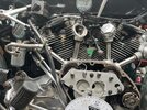
So with zero valve clearance set and clocks zeroed on base circle you turn camshaft of first cylinder for equal readings - in photo 4.37mm MK 2 cam.
So then get the Dremel and mark one tooth closest to some engine case and set a corresponding chisel mark. Once done turn second cam for equal lift and have same marks on gear and case.
So then you can assemble the engine with all components , crank , springs, and all. When dealing with timing gears you have the timing disc on the crank end and by applying the piston stop on spark plug stud in clockwise plus anticlockwise positions readings halved and disc set to zero on TDC you then get crank back to 4 degrees BTDC for rear cylinder, idler gear already pushed into tight mesh in both cam gears, and in this 4 deg set you get the half time gear out and try all 5 slots for best mesh with the mainshaft key and slip it onto crank end. The first camshaft was aligned with its marks of course before for equal lift at 4 deg.
For front cylinder you turn the crank forward for - ah- 410 degrees ? - that would be 406 degrees (-4) on the disc? - hope I did not mess this up at late night writing.
So in this crank position the front cam gear at Dremel/chisel marks aligned should be put into mesh with idler gear nicely. When it is out a lot by a half tooth you´d decide on pressing the cam out of the gear and try better.
I was lucky with all Andrews cams so somebody else will better tell about how to go with some out of synch cams driven by idler gear, some jig would be used for this job I think.
With alignment marks on gears and case you do not care about hunting gears at all, the timings can be checked any time later, unless you get new cams and gears so you´d do fresh marks on these parts.
Vic


Vic
So with zero valve clearance set and clocks zeroed on base circle you turn camshaft of first cylinder for equal readings - in photo 4.37mm MK 2 cam.
So then get the Dremel and mark one tooth closest to some engine case and set a corresponding chisel mark. Once done turn second cam for equal lift and have same marks on gear and case.
So then you can assemble the engine with all components , crank , springs, and all. When dealing with timing gears you have the timing disc on the crank end and by applying the piston stop on spark plug stud in clockwise plus anticlockwise positions readings halved and disc set to zero on TDC you then get crank back to 4 degrees BTDC for rear cylinder, idler gear already pushed into tight mesh in both cam gears, and in this 4 deg set you get the half time gear out and try all 5 slots for best mesh with the mainshaft key and slip it onto crank end. The first camshaft was aligned with its marks of course before for equal lift at 4 deg.
For front cylinder you turn the crank forward for - ah- 410 degrees ? - that would be 406 degrees (-4) on the disc? - hope I did not mess this up at late night writing.
So in this crank position the front cam gear at Dremel/chisel marks aligned should be put into mesh with idler gear nicely. When it is out a lot by a half tooth you´d decide on pressing the cam out of the gear and try better.
I was lucky with all Andrews cams so somebody else will better tell about how to go with some out of synch cams driven by idler gear, some jig would be used for this job I think.
With alignment marks on gears and case you do not care about hunting gears at all, the timings can be checked any time later, unless you get new cams and gears so you´d do fresh marks on these parts.
Vic
Vic