ET: Engine (Twin) Main bearing race splitting?

milohiscox

Forum User
VOC Member
I have split the cases on my rapide (first time for me) and am trying to get my head round what’s inside.

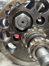
Both sides of the flywheels have heavy scoring on the nuts. I guess this suggests both main bearing races have ‘walked out’ in the past into the flywheels.

Both main bearing races are tight in the cases right now, and heavily staked, suggesting someone got them back in ok.

What I can’t work out, is what’s happening with the inner edge of the larger timing side bearing race. It looks like it’s got a lip, or as if it’s splitting (both unlikely?), or something has worn a groove into it (but what?). Drive side races look ok.

All I can think is when the race walked out, a bit of crankpin nut was broken off and got lodged in there and scored a groove. But then why wouldn’t they replace the race with a new one when they put it back in?


IMG_2355.jpeg
 

Attachments

  • IMG_2354.mov
    19.5 MB
  • IMG_2356.jpeg
    IMG_2356.jpeg
    340.8 KB · Views: 47
  • IMG_2334.jpeg
    IMG_2334.jpeg
    461.8 KB · Views: 46

davidd

Well Known and Active Forum User
VOC Member
What I can’t work out, is what’s happening with the inner edge of the larger timing side bearing race. It looks like it’s got a lip, or as if it’s splitting (both unlikely?), or something has worn a groove into it (but what?)

The staking looks horrible. What you are worried about occurs often. The case is thin in that area, and it does break out. I assume much of it is done by heavy-handed handling during rebuilds. Here is a shot of a crankcase I assembled several months ago:

DSCN6351 (2).jpg


The timing cover is installed, so you are looking at it through the bearing hole, and the quill would be installed in that hole. I installed the timing cover because I noticed a hole in the oil pump housing. I have an 1-1/4" long screw in the hole, and it is visible in the threaded hole, but a longer screw might have broken through, or there could have been considerable debris in the threaded hole. I cleaned up the gap in the back wall of the bearing pocket so there was nothing sharp or easily broken off remaining.

David
 

chankly bore

Well Known and Active Forum User
Non-VOC Member
The person who put the race(s) back in needs to be put up against a wall. The only way to restore this motor is to go along to someone like Maughans with a large wallet. Start with the big-end and work upwards and outwards. Otherwise you're building on mushy sand, so to speak. I don't think the inner timing side main had a lip, because with the reduced width the rollers run very near the edge and in any case, fitting it would not be possible. Some owners have fitted lipped full width bearings to the inner drive side to stop, or slow the dreaded "walkies."
 

greg brillus

Well Known and Active Forum User
VOC Member
Very common issue there........probably at least 50 % of engines I do save the singles, which seem less prone to it need the bearing housings reclaimed.......not as drastic and super expensive as one might think, get it done on a CNC mill way quicker and more accurate than a manual mill.......We bore out the timing side first after clocking up off the smaller ET 94 bearing housing.......bolt the drive side case to the timing side with several through bolts/studs.......then bore the drive side oversize right through.......timing side has a thin walled (2mm max) thin steel sleeve made up and pressed onto the new ET 92 outer race, then the case half is heated and the race assembly dropped in.......this must be done AFTER the smaller ET 94 bearing and the oil pump sleeve is installed. Drive side we make a hat section steel sleeve, thicker walled than the timing side, this to make room for the new circlip grooves.......machine the bore to within a few thou, cut in the circlip grooves, heat the case and install the new sleeve, less the bearings........we then hone the drive side housing to 2.4975/ 2.498" allowing no more than 1 to 1 1/12 thou interference, any more and the new C3 bearings will be too tight and the inner race plus the center race of the E 91 bearings will be too tight........We have always done the sleeves in steel not brass or alloy........generally I do not anchor the sleeves into the housings using countersunk screws or similar, this I feel because after machining, each housing is getting quite thin, and I've seen race engines with this done, that have totally split the main bearing housing through where these screws were drilled/taped into the housing.......it seems like a huge job, but it's not actually that bad. As for the crank.......well that is a different story.......if the wheels have shifted which is very likely, it will need attention.......quick check is simply put a 300 mm steel ruler across the edge of the wheels adjacent to the big end, check it on both sides.......if they show a gap, then the crank is out of true and will need to be looked at..........Good luck with it.......Cheers.
 

greg brillus

Well Known and Active Forum User
VOC Member
Assessing cranks is a bit like checking barrels and wheel hubs.......there is always more to check than you might think.......yes you can shift it 2mm so long as it's just in the rotation of one wheel verses the other.......if it's out say top to bottom then you've probably got a more serious problem........if that were the case, then its likely one side of the big end pin has gone into that wheel crooked and broached its way in........I've seen it done, the only fix is to bore the big end holes bigger and get an oversized big end for it.......Of course the first thing to check on any old crank is the condition of the mainshafts.......if these are badly worn where the bearing races sit, the splines are in poor shape, and/or if the shafts (especially the drive side) has spun in its wheel, then you need think twice about how you progress from there.......If a bike is fitted with an electric starter kit, it can and will rotate the shaft in the wheel.......this can actually lock up the crank solid......seen it happen.......Cheers.
 

milohiscox

Forum User
VOC Member
Greg - thanks for the tips. The drive side sleeve - do you put the hat on the inside or outside of the housing? Does it really need the hat or is a good interference fit (0.004”?) and loctite enough to hold the sleeve and resist any thrust through the circlips?
I wonder if anyone has ever kept the original circle grooves and put two shorter sleeves either side of them? Of course the sleeve would have to be thinner than the depth of the circlip groove.
 

greg brillus

Well Known and Active Forum User
VOC Member
The hat is on the inside......it gives a better purchase for extra strength.......0.002" interference is enough.... best to heat the case in an oven if possible, to around 180 degrees.......200 is actually too much.......the sleeve wall thickness does not need to be too thick, the circlip grooves do not need to be as deep as standard as they are anchoring into steel not alloy.........because the bore is long and open, you can hone to the desired finish size more accurately, as doing this on the mill is a bit risky........with the timing side after the steel sleeve is pressed onto the new bearing outer race, you can carefully trim the size of the OD of the sleeve to give the correct shrink fit into the bearing housing.......again not more than 0.0015" interference.......once the drive side sleeve is installed, the interference fit for the bearings on this side need to be very small, less than a half a thou, as you are pressing steel bearings into a steel sleeve.......I do all this work with a competent machinist who has the skills and knowledge to get it right ....... We have never made the drive side sleeve any other way than one piece........we have done many in this way with no issues........Cheers,
 

davidd

Well Known and Active Forum User
VOC Member
Bearing Steel Sleeve.PNG


The sleeves in this engine were both built with a similar construction. They are quite thick compared to Greg's. On the drive side, the circlips are cut into the sleeves. John Renwick did the job for me many years ago.

As Greg says, the clearances are important. If they are too tight, the sleeve will close down on the bearing and it won't turn when installed. I have the drive-side photo only.

David
 

oexing

Well Known and Active Forum User
VOC Member
I did just that in my engines, two short alu adapters at both sides of the only remaining circlip , loctited in. For line boring you take out the circlip certainly.
What puzzles me is, nobody went my idea of having readily available and MUCH stronger metric roller bearings with 30x62x16 or 20 , type NU, NJ , NUP whatever lipped type you like, certainly with PA66 cage, no brass or steel ever again ! So you do not have to weaken the engine case even more for sleeving oversized bearing housings and restore the 63.5mm standard size. With 62mm you just press in an alu liner a bit smaller i.d. for line boring later. So with modern bearings you will never have that silly walking outer race again, a stronger crank bearing system additionally. Yes, you´d have an adapter sleeve on the mainshafts for 25.4mm to 30mm metric - drama ??
Plain outer races, no lips - never seen that in continental engines - they like walking in their seats you know . . . . plus engine assembly is silly with rope trick . . . .
And no, I never mess around with lapping or honing new races for extra "clearance" as you get roller bearings ready made with standard clearance anyway, no need for extra. Remember, you never run an engine in cold state when it is a gasoline engine. Yes, you may have a little "preload" on rollers when you made a correct shrink fit for outer races calculated for just secure fit up to 100 degrees C and freeing above that only. But that is no concern, you only warm the case for assembly when you feel the bearing rollers do not want to slip together in cold state. When you lap the races for clearance in cold state I believe you get sloppy bearings when in hot state, would not want this - and I never ever had problems with this approach. Nothing to worry about a little preload on rollers when cold, taper rollers on lathes are preloaded all day , sitting in all-steel castings, no heat growth ever to relieve them. Or look at cylinder roller bearings in mill spindles, some got types with slightly tapered inner races sitting on taper shafts for setting preloads by pressing them up the taper . You cannot have ANY play there, instead preload for a solid mill head, no alternative here ! Rollers are rollers, taper or cylindrical, some preload is allright, in the Vincent case they even run with play most of time with heat growth of case.
Well, speaking Vincent you want cranks with minimum runout of mainshafts, so this is priority for any engine, no great idea to care for poor runout by having sloppy bearings.
Certainly shrink fit in an all alu case is more than half thou here, in fact rather two thou minimum for gripping the outer races in warm engine. So when dropping in the outer race you want 100 degrees like in any other engines with alu cases - when not horizontally split like on Japanese multis.
Well, that´s me, radical as ever - and thanks for the last photo above - staking - makes me vomit . . .

Vic

P1070655.JPG


P1070661.JPG


P1070540.JPG


P1070544.JPG


P1070831.JPG
 
Top