Wheel Building

oexing

Well Known and Active Forum User
VOC Member
Regarding MM´s "200 percent original" hubs and all, look at the "safety nuts" in the photo: Some are the split safety type, some sort of nylocs, and some bolts too short for becoming safe from reaching the locking material. So much for describing all original components. They grabbed what they got at the works for assembling bikes in short time.

Vic
 

Cyborg

Well Known and Active Forum User
VOC Member
Don't think for a second that you're fooling me. You wrote this just to make me feel bad that your lathe is bigger than mine. Mine doesn't have the swing for an 8"-long spoke. On second thought, I'll machine half the head in my lathe, stop the motor, flip the spoke by 180°, and machine the other half. That'll show you...

Based on everything that has been written so far, and assuming when I make more measurements of my assembled hub I don't find a problem with the idea, my present plan is to machine a jig to allow me to press the "wings" of my spoke flanges a further ~0.065" (i.e. an additional 6%) to allow the heads of the spokes to pass through.

I’m hurt that you would think that I’m try to make you feel bad.
Rather than make a holder with the spoke nestled in that humungous T slot, I‘m assuming it would be easier to bore a small hole in soft jaws to provide an exit for the shank of the spoke. That way the neck will be firmly held in place and properly aligned. This is assuming I get to the point where I want to reduce the heads on the inners. I asked Devon Wheel what size their spoke heads are, so maybe that’s an option, because I am yet to buy spokes. Reducing diameter of the heads on stainless spokes ( no plating to worry about) slightly may be preferable to reshaping the flanges. The smaller head might clear the spoke next door.

21050F23-38C4-4597-85AE-A2ABA8C8FCA4.jpeg
 

Shane998

Well Known and Active Forum User
Non-VOC Member
I'll check the paint thickness when I have it apart later today or tomorrow, and I won't apply new paint where it doesn't belong.

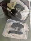
I partially disassembled the rear hub yesterday, removing the brake plate and exposing the tapered bearing.

View attachment 46525

At this point the 10 H19/1 hub bolts also are revealed (only 5 are shown in the drawings, presumably for parts dating from an earlier age). I'm guessing that the portion of the bolts that fit in the brake hub are knurled in some way to keep them from turning when the nuts are attached. The next photograph shows how close these nuts are together, having evolved from the earlier 5-bolt pattern which would have given them a more generous spacing,

View attachment 46526

Based on the above, I don't see why there would be any particular problem fitting the spokes before tightening the flanges. That is, it doesn't appear there would be an advantage to having a sufficient gap between brake hubs and spoke flanges to insert the spokes after the flanges were tightened. Unless, of course, a spoke needed to be replaced in a wheel that was already laced. Comments?

On the other hand, apparently some people use a spacer (shown in red) to allow room to install and remove spokes.

View attachment 46528

However, the steps in the hollow axle noted with arrows provide hard stops for the bearings, and the brake plates provide hard stops at the other end. The H17 shims correct for production tolerances to give the desired end float. Unless the red spacer is thin enough that the correct end float can be achieved with no, or thin, shims, a red spacer is a bodge, not an option. Again, comments please.

Note that in the above drawing I've replaced what is shown in the Alternative Spares manual for the bearing and shims with what is in the Vincent spares manual. The inset below is from the Alternative manual, showing a "spacer" next to the bearing, which isn't shown in the Vincent manual, along with what are probably the K17 shims, although they aren't called out with part numbers.
I assembled hubs and flanges and drums Then removed drums leaving a few bolts (they stay in place ) to keep position of flanges Then get some other shorter bolts and nuts to fix flange in place say 3 spaced around the hub All hub bolts out now Then you can lace and true the wheel without heavy drums once the spokes are all in and tensioned you can remove the temporary bolts and nuts and the flanges won’t move Then refit drums As for replacing broken spokes you would have to remove wheel strip tyre etc so the loosening off hub bolts enough to create clearance if needed should be reasonably easy (note I have not replaced spokes so this is only theory ) Would be interesting to know how they did it in factory As Bill says just my thoughts
 

Attachments

  • AFC27C95-D5F7-4EAC-86D4-75C82EA2D65C.jpeg
    AFC27C95-D5F7-4EAC-86D4-75C82EA2D65C.jpeg
    243.8 KB · Views: 24

chankly bore

Well Known and Active Forum User
Non-VOC Member
If a spoke breaks at the lower end, as an embrittled chrome-plated (this was the 70's, remember) one did on my Comet, I replaced it without even removing the wheel from the bike. As long as it is a freep shorter than the one you pull out, quite safe.
 

Magnetoman

Well Known and Active Forum User
VOC Member
The drums are fixed firmly to the flanges on the hub. The distance between them does not change.
OK, we may be addressing different things, so I'll try again. My interest is in understanding how it might be possible to increase the gap at the edge of the spoke flange to allow spokes to be installed when the flange is totally tightened against the drum. I learned from something I read here or elsewhere that shims are available to go between the flange and drum, which would be an easier solution than making a jig and bending the flanges. But, is such a shim a reasonable solution, or is it a bodge? To address that question:

The next photograph shows the hub and axle, showing that the inner race of the bearing presses directly against the brake plate on one side and against the raised shoulder of the hollow axle on the other side (plus shims).

1640Hub01.JPG


This is seen better in the next photograph, where the gap is where the brake plate goes.

1650Hub02.JPG


Tightening the H13 nut on the bottom in this photograph firmly clamps the brake plate against the inner race. Aside from the H17 shims (or pages cut from K17), the length of the hollow axle determines what thickness everything between the two H13 nuts can have. If someone wanted to use something thicker, like a badly-made reproduction brake plate that was thicker than the original outboard of the bearing, the only way that would be possible would be if the extra thickness could be compensated for by removing shims, or by having the H13 nuts a few turns less on the axle, or both.

Reusing a previous drawing, the red spacer would increase the overall thickness of everything between the bearings. Since this is inboard of the bearings the only possibility for compensation would be the H17 shims that are between the inner race and the shoulders of the axle.

1592Spokes.jpg


Or, have it got it wrong?
 

timetraveller

Well Known and Active Forum User
VOC Member
I'm not sure if this is relevant as I am having some difficulty understanding the problem but the red shim does not increase the overall thickness of everything between the bearings. It does not affect the distance between brake plates other than it might be necessary to use extra ahims on the outside of the inner bearing in order to allow clearance between the brake plate outer edge and the outer edge of the brke drum. Sorry if this is addressing a different problem.
 

TouringGodet

Well Known and Active Forum User
VOC Member
VOC Forum Administrator
VOC Forum Moderator
Adding a shim between the spoke flange and the brake drum pushes the drum outward, towards the brake plate. I suspect you would then need to add shims on the outside of the wheel bearing, between the bearing and the brake plate, to correspondingly push the brake plate outwards by the same amount. Nothing changes for the shims on the inside of the bearing, between the bearing and the flange on the hub.
 

Michael Vane-Hunt

Well Known and Active Forum User
VOC Member
I had the problem of the spokes touching the back of my new Shadow brake drums, the spokes had made little dents in the back of the drums. I got all four drums skimmed where the spokes were touching. Not much needed to be removed. The drums were thick enough to make no structural difference to them. After rebuilding the wheels I can slide a feeler guage between the spokes and drums. Done 30 or 40 thousand miles and no problems so far. I built the wheels up as mentioned in Shane's post #53 and checked the runout again after the drums were fully installed and tightened up. I also check the the 499 nuts periodically as well as the sprocket 91 nuts.
 

Cyborg

Well Known and Active Forum User
VOC Member
Room for a thicker plate or shim could be accommodated by turning the thickness of the shim off the cam bush steady sleeve H27/1AS, or in the case of alloy plates (Lightning Flash) just toss the steady sleeve all together.
That applies to the rear… front is another story.
 
Last edited:

Robert Watson

Well Known and Active Forum User
VOC Member
MM Robert is correct in this and when you have got further into your dismantling you will understand why, There is also the matter of the shape of the bolts which hold the brake drums on to the hollow axles, spoke flanges etc. There are two types of these but when and where the change was made I do not know. There is the type described by Robert with the offset cylindrical heads which are constrained from turning by the interference between the bolt heads and the bearing housing. The other type had a hexagonal head with one flat cut lower than the other five. That undercut flat sits against the bearing housing. Both type work well.
More than 2 types of hub bolts TT - I can get to at least four.

Three are shown on this picture of
A large round head with on flat milled - center
A standard hex head with one flat milled deeper - right
A stamped two flat head, I have seen quite a few of these. -- left
The fourth being the round eccentric head type

Also nuts
with the red locking material, like MMs
A modern nyloc hiding behind the center bolt
and the split rim type not shown but on MM picture


20220110_183827[1].jpg
 
Top