TDC Timing Valve

pete4000

Active Forum User
VOC Member
I've just finished to rebuilt the engine on my black shadow and I have questions regarding the timing valves, because I'm not sure for the half time pinion dot.

In the Richardson book, Fig 56, when all the marks mesh (cam pinion, idler cam, and half time pinion), the half time pinion should be 4° BTDC for the rear cylinder ? Is that correct ?

Also, when the rear cam pinion mesh whith the idler cam, the inlet valve and the exhaust valve are in balance for the rear cylinder? and the valves for the front cylinder are closed ? Is that correct ?
I just want to make sure that everything is in order.
Thanks for your answers.
 

mercurycrest

Well Known and Active Forum User
VOC Member
I always used TDC to line the marks up. Then, one day I looked at the Instruction Sheets and read about the 4 degrees. Why would you have marks so as not to have to use a dial indicator, and/or timing wheel, then still have to use a dial indicator and/or a timing wheel? I very carefully put the Instruction Sheets back on the shelf and continued as before, with no bad results as of yet.
Cheers, John
 

bmetcalf

Well Known and Active Forum User
VOC Member
On jtan, the consensus (and I use the term loosely) was that the midpoint of the overlap should be at TDC. Conventional wisdom is that retarding from that a few degrees makes more power at higher revs and advancing helps lower rpm power/torque. Marks, of course, are dependent on accuracy when pressing the wheels on the cams.

Differing opinions accepted.
 

pete4000

Active Forum User
VOC Member
Thanks John and Bruce for your answers. It is more clear for me.
The last owner of the bike remove the exhaust lever and all the exhaust lifter mechanism. (Fig 58 - Page 109 Richardson). He told me that it was not necessary to use it when starting the bike . What are your opinions ? Should I put it back ?

Pete.
 

Len Matthews

Well Known and Active Forum User
VOC Member
The problem arises when there is no known history of the Half Time Pinion. Each one was marked at the time of initial assembly at the Works so in the intervening fifty or sixty years there's no guarantee your bike has still got it's original. The old "Valves rocking at TDC" tecnique is a reasonable starting point.
 

Len Matthews

Well Known and Active Forum User
VOC Member
Thanks John and Bruce for your answers. It is more clear for me.
The last owner of the bike remove the exhaust lever and all the exhaust lifter mechanism. (Fig 58 - Page 109 Richardson). He told me that it was not necessary to use it when starting the bike . What are your opinions ? Should I put it back ?

Pete.

Yes!! without doubt. No point in over stressing the Kick Start mechanism. What's more, you need to have some way of stopping the engine (assuming it's magneto ignition.
 

timetraveller

Well Known and Active Forum User
VOC Member
Hello Pete4000, Consider that your bike is now about 55 to 60 years old and who knows what kind of people have worked on the engine in the past. As Len says there is no guarantee that any of the marks are where they should be and as you have rebuilt the engine it should still be out of the frame. Therefore you now have a good chance to do the job properly by using a dial gauge on top of the valve stems. My advice is to use the timing as set up by the original designers of the engine and do not pay attention to 'experts' who will tell you how advancing or retarding the timing will affect the performance. Can any one of those 'experts' show you results from a series of brake test? Often people do not realise that Vincent timing is taken at five thou lift, 125 microns if you have to use a metric dial gauge. My advice is measure the whole of the lift curve for both cams on both cylinders. If you do not have the patience to do that then at least measure those eight opening and closing points. Only once you have those details can you set to and work out where the best compromise timing should be to get all the opening and closing points as near as possible to the original timing. It might mean moving the half time pinion around on it key-way, five key-ways and 24 teeth give you a vernier arrangement to within 3º. If all else fails then you might have to press out one cam and put it back into its pinion slightly turned from where it was. All this might seem tedious but once you have done it you will be able to use the bike, totally satisfied that the timing is correct and if the bike does not go as it should then all you have to get correct is ignition timing and fuel mixture strength. Bon Chance.
 

bmetcalf

Well Known and Active Forum User
VOC Member
Good points. The "conventional wisdom" I mentioned was what I applied when I found that one cam was either 1/3 tooth advanced or 2/3 retarded, then chose the former. I would imagine that that difference between cylinders would also be hard to see on a set of dyno sheets.

Also, I forgot to say that I was advised to measure at .050" (1.25mm) lift to be well clear of the quieting ramps of the modernized MK3 cams.

What I use when installing my cams is to align the slots per the illustration in Richardson, with the rear piston at TDC, after confirming it with the dial gauge and timing disc when I bought the cams 25 years ago.

Hello Pete4000, Consider that your bike is now about 55 to 60 years old and who knows what kind of people have worked on the engine in the past. As Len says there is no guarantee that any of the marks are where they should be and as you have rebuilt the engine it should still be out of the frame. Therefore you now have a good chance to do the job properly by using a dial gauge on top of the valve stems. My advice is to use the timing as set up by the original designers of the engine and do not pay attention to 'experts' who will tell you how advancing or retarding the timing will affect the performance. Can any one of those 'experts' show you results from a series of brake test? Often people do not realise that Vincent timing is taken at five thou lift, 125 microns if you have to use a metric dial gauge. My advice is measure the whole of the lift curve for both cams on both cylinders. If you do not have the patience to do that then at least measure those eight opening and closing points. Only once you have those details can you set to and work out where the best compromise timing should be to get all the opening and closing points as near as possible to the original timing. It might mean moving the half time pinion around on it key-way, five key-ways and 24 teeth give you a vernier arrangement to within 3º. If all else fails then you might have to press out one cam and put it back into its pinion slightly turned from where it was. All this might seem tedious but once you have done it you will be able to use the bike, totally satisfied that the timing is correct and if the bike does not go as it should then all you have to get correct is ignition timing and fuel mixture strength. Bon Chance.
 

mercurycrest

Well Known and Active Forum User
VOC Member
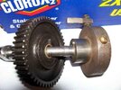
I have a tool that is easy to make up and I'd recommend each section have one in their tools to lend bin. I hope I managed to post it correctly. The easiest way to make it is by using a know properly indexed set of cams. Once it is done it only takes a matter of seconds to tell if your cams are right or not and if you're very careful you can do a pretty good job of aligning them with it for pressing together. In the picture the pin just above the 1/2" shaft fits snug into the slot in the cam shaft and the 3/16" square piece bolted to the rim is ground to a triangular shape where it fits into the marked teeth on the pinion. This is set up for a front cam. the brass screw that isn't being used is for the rear cam. Just swap the triangular piece from one position to the other to check front or rear cams.
I hope this all makes sense... technical writing is not my forte'

Cheers, John
 

Attachments

  • Cam indexer .jpg
    Cam indexer .jpg
    16.4 KB · Views: 109
Last edited:

mercurycrest

Well Known and Active Forum User
VOC Member
Let's see if this works twice in a row.:)
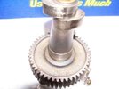
Here is a front camshaft with the dowel in the indexing slot and the pinion with the two dots facing down on the triangular 1/4" piece (not 3/16"). You need to shim the pinion wheel up a bit to start it in your press, then remove the indexer and press everything home.
Cheers, John
 

Attachments

  • camshaft alignment.jpg
    camshaft alignment.jpg
    11.4 KB · Views: 85
Top