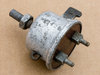
Hi all, managed to find an early brake switch, on testing it works but requires a lot of pressure to make contact.
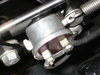
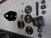
Was wondering if anyone has had one of these to bits before, at least you would have to un-crimp the edge but not sure how it comes to bits with the lever slotted though the casing.
I imagine it must be something like the lucas switch internally and wondered if an adjustment could be made so it made contact with less pull on the lever.