You are using an out of date browser. It may not display this or other websites correctly.
You should upgrade or use an alternative browser.
You should upgrade or use an alternative browser.
Misc: Everything Else Air Fuel Gauge 02 Sensor Lambda Sensor
- Thread starter Cyborg
- Start date
I managed to get the Innovate to work on a standard Comet with muffler, but despite trying several times cannot get a reading on the TTR's 2" open pipe. Now I know why. When I made the pipe, I made one first but my welding was a bit scabby and wouldn't polish up too well (SS) so I tacked up a second one and had the local food piping shop weld it up, absolutely beautiful but I bet would give identical readings to the blemished one. I'll have to dig it out and weld a bung in it ---- never thought of that..

It actually would be quite straightforward to answer. Someone with a modified pipe like mine, where the sensor barely protrudes, checks the AFR at all throttle settings, then slips a Bunsen valve over the end of the pipe, and checks again.
The wording with "someone" and "like mine" wasn't accidental. It's easy to get lured down some else's rabbit hole when you still have plenty to do down your own.
Has someone answered the haunting question about the Bunsen valve yet? While your at it.. as previously mentioned, if we can believe the “thumbscrew dyno run” in the video (post 77 at 7:30) the installation of your Innovate sniffer has an effect on A/F ratio, especially with the overlap on the GS cam. Now you can record the data from the bung mounted sensor and then make another run with the Innovate probe installed. Still using the data from the bung mounted sensor, that someone can answer the other nagging question... How much “observer effect” is caused by the probe.... and don’t bother trying to feed me anymore crap about it being my rabbit hole.
got consistent results with a M8 nut brazed in back side of pipe about 12" from port
As discussed below, even a little air leaking into the pipe is too much air.my welding was a bit scabby
I hate it when someone else's rabbit hole merges with mine. Sigh...and don’t bother trying to feed me anymore crap about it being my rabbit hole.
Progress here is on a temporary (I hope) hold because the garage A/C failed yesterday afternoon and we face predicted record-breaking heat through Friday. The repairman is due in a few hours but then I/we/he has to figure out how to find space amidst the clutter... er, I mean, extremely well-organized contents to plant a 12-ft. ladder to reach the condenser in the 13-ft. ceiling.
It's important when navigating this rabbit hole to keep in mind that "reversion" refers to two separate, but interrelated, phenomena. In the case of those dyno tests, it refers to the pressure wave that reaches the end of the pipe and then bounces back just in time, and with the right positive or negative amplitude, to either keep all the exhaust from escaping from the cylinder, or to help suck additional charge into the cylinder. Either way, performance can either suffer or benefit in the rpm range where such "pressure reversion" takes place. Here, essentially no physical transport of air/CO2 within the pipe has to take place. The reason is, pressure applied at one end of a long tube that's sealed at the other end also raises the pressure at the sealed end without transporting any of the additional gas molecules that were applied at the open end to raise the pressure.
For AFR measurements, the issue is the actual transport of O2 molecules from the open end of the pipe up some distance into the pipe (albeit, not nearly as far up the pipe as to reach the cylinder). In "reversion" of this type there is physical transport of O2 molecules, and if any of them make it as far as the AFR sensor they will screw up the measurement.
---- sidebar ---
The stock, open exhaust pipe on my Catalina's is 1.65"ID and 51" long, for a total volume of 1.79 liters. This would be enough to fill the cylinder more than three times over if all of it "reverted." The modified pipe and silencer I have on it now for AFR testing has the sensor 18" from the end, so if a volume of 647cc were uniformly drawn back into the cylinder then fresh air would reach the sensor, which it doesn't. Interestingly, the sampling tip of my unmodified Innovate was 9.67" long, for a volume between it and the exit of the exhaust pipe of 339cc, and there were issues of reversion with it. However, that's not to say that at least 339cc is sucked back into the cylinder on each cycle. But it does that that enough is sucked far enough back in that it, along with mixing, results in at least some fresh air reaching ~9.7" into the pipe.
Keep in mind that an AFR meter doesn't actually measure the AFR. It measures the amount of free O2 (or deficit of free O2) from which the controller then calculates the AFR. If the sensor detects no O2 whatever the controller displays that as '14.7'. Because the controller displays results calculated from deviations from 'zero' it takes only a tiny amount of wayward free O2 to generate a bogus result.
------ end sidebar ---
Turning to the video, the "major dip in the midrange" they found to one extent or other always was accompanied by an AFR that flatlined at or below 10:1, i.e. very rich. Sticking bolts of various kinds had an effect on the h.p. in the ~2500-3500 rpm range, but always the mixture was too rich. This means the "reversion" the narrator talked about only refers to pressure waves, not to O2 being sucked back up the pipe. When they changed the jet to lean the mixture the AFR indeed showed a leaner mixture at higher rpm, but it still flatlined at 10:1 in the midrange.
The video shows unlabeled red and blue curves on most of the plots so it's not always possible to know what's what. But, as far as I can tell, within experimental error the various bolts had a small effect on the h.p. in the midrange but no effect on the AFR.
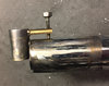
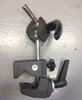
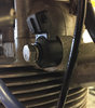
OK, back to Cyborg's branch of the rabbit hole. His question is "How much “observer effect” is caused by the probe...."? In the interests of maintaining cordial international relations with our neighbors to the north, after testing the new Mark II instrumentation system I'll shove a probe up the exhaust and see what effect the disruption causes. The answer could turn out to be "a lot," given what the attached photographs show.
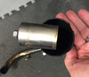
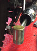
The first photograph is a side view of the sampling probe in a 1-3/4" OD pipe, and the second is an end-on view. The paired 3/8"-OD sampling tubes block a little over 10% of the exhaust pipe over a considerable length, and the fumes that manage to get past that obstacle then encounter the fat mount for the sensor at the end of the tube. As the third photograph indicates, I can at least make the life of the exhaust fumes a little easier if I attach a new mounting point to the probe a few inches upstream from the current mounting point.
In the time it has taken to write this, interrupted by lunch and the visit of the A/C repairman, I again have life-giving cool air in the garage. However, the day had a 100 oF head start on the cooling so it is only now getting down to a bearable temperature. As an aside for people interested in magneto capacitors that fail, it was the capacitor in my four-year old A/C unit that had failed. The repairman told me they service units made in the 1950s that still have their original capacitors, but when the mandated change was made to environmentally friendly materials the lifetimes dropped to anywhere from 1 to 10 years. Replacing failed A/C capacitors is the largest category of their work.
Attachments
Addendum. That video Cyborg links to in post 77 shows the importance of using an air/fuel gauge, although the narrator of the video basically ignored that data and as a result completely missed the point and came to the wrong conclusion. Because of "reversion," with straight pipes on their engine there is a dip in mid-range h.p. accompanied by a too-rich mixture. If they had understood the actual connection between cause and effect they would have realized the problem was with their carburetor, not with reversion due to resonance in the exhaust pipe. Similar to thinking the problem is a fever and trying to cure it with aspirin, missing the fact the actual problem is strep throat.
At one point in the video they installed a smaller main jet which caused an increase in AFR at high rpm, but the problem was at lower rpm. Rather than take advantage of the reversion by re-jetting the appropriate circuit in their carburetor that dominates the mixture in that rpm range -- assuming the design of their S&S carburetor actually allows such an adjustment -- to give the correct mixture and benefit from the increase in h.p., they blamed the mid-range problem on the exhaust pipe, rather than their carburetor, and tried to kill the reversion.
For our purposes any possible limitations of the design of S&S carburetors aren't important, only whether or not an obstruction in the exhaust pipe interferes with the dynamics of the engine in such a way to affect the AFR. I hope to have the answer to that before much longer, although the current ten-day forecast is for temperatures 102-106 oF that entire period.
Addendum: I've now watched that video from the start, rather than the midway point, and it's worse than I thought. At the 5'50" point the narrator says "Tuning a carburetor to fix an exhaust problem is somewhat like putting your arm in a sling to cure a headache." This is totally wrong. Tuning the carburetor is exactly what you need to do to fix an exhaust problem. Further, that resonance isn't even a "problem," it's how additional h.p. can be extracted from the engine. But, only if you realize you have to tune the carburetor. Sigh...
Last edited:
How do you plan on attaching your knock sensor? Once you finish exploring your rabbit hole, you should ( must?) follow the branch that leads over to the other side. You could have some fun playing around with intake runner length and velocity stacks?
Been thinking that your lovely bride should just give up and cash in her 401k...buy you a dyno and not have to chase you around the desert in 100+ heat.
Been thinking that your lovely bride should just give up and cash in her 401k...buy you a dyno and not have to chase you around the desert in 100+ heat.
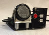
I completed my Mark II instrumentation package. The Bosch AFR sensor should be turned on only after the engine is running so I positioned the on/off switch and used a large button to activate recording, all the better to operate both with a gloved finger. The LED next to the button flashes when it's recording and the LED below it flashes when triggered by the knock sensor. Not that it will matter very much, if at all, in practice, but since the LED that came with the knock controller is red I used a different color LED (orange) to indicate recording.
Since the outer ring of LEDs on the gauge serves to give an "analog" reading of the AFR, and since they're brightest when viewed head on so, and since I can't tilt the platform (because then I couldn't use the internal accelerometers), I tilted the gauge in its mount.
On the bottom of the platform is an array of seven nuts for attaching it to the Manfrotto clamp with 33 lb. rated capacity (the package weighs just 3 lbs.). I gave the platform multiple attachment points for maximum flexibility in mounting on various motorcycles. It's now mounted on the Catalina ready to go but a heat wave as well as other obligations likely means it will be a few weeks before I'll be able to test it on the road.
Meanwhile, with Mark II finished (for now, at least), I turned my attention back to my original Mark 0 system, consisting of an Innovate LM-1 for the AFR coupled to an LMA-2 for throttle position and rpm. The LM-1 is limited to capturing only 44 min. of data in its internal memory (vs. >500 hrs. on an SD card with the Mark II system). However, for most purposes the limitation of "only" 44 min. of data at a time isn't much of a limitation at all. From my experience, when the LM-1's display indicates the jetting is wrong I want to head back to base to change it right away. And even when it indicates it is fairly good there isn't any point in capturing data for longer than that before heading back to base to change it to be even better.
Anyway, since for accurately determining the proper jetting the Mark 0 is WAY better than no system at all, rather than abandon it entirely I spent a few minutes this weekend modifying its mount so it now fits on the same type Manfrotto clamp as does the Mark II (I have more than one such clamp). I also painted it. This gives me two complete AFR systems, the Mark II that is "permanently" installed on the pipe and the Mark I that is attached to the probe that I'll use to explore Cyborg's rabbit hole.
When the 100 octane fuel was used up I filled it with 91 octane. I thought the knock sensor wasn't working because I didn't see it flash on the 2 miles out of the neighborhood. But, when I did an acceleration run I thought I might be hearing pinging, and when I looked down the knock light was flashing. Retarding the spark at that point turned off the light (and reduced the acceleration). So, even 8:1 has issues with the highest octane available at the pump. At least, there are issues when doing an uphill acceleration run starting at the low end of 4th gear speeds. By the way, if I hadn't had the knock sensor to consult, the faint sound of the pinging over the noise from the engine and wind might not have entered my consciousness
I assembled 35 Gold Star factory dyno curves covering all configurations (road, scrambles, Clubmans,...) of 350cc and 500cc machines from ZB through DBD. I've then been "calibrating" an engine simulation program by feeding it as much actual data as I can collect to eliminate as many variables as possible while fitting the measured curves. So, various combinations of heads, carburetors, velocity stacks, exhaust pipes, silencers, etc. found themselves attached to my flow bench over the past few months.
The idea behind doing this is that, once "calibrated" by fitting known curves, the program will let me "build" engines in the comfort of my office in any desired configuration (e.g. trials cams in a Clubman with a long intake runner) and then quietly "measure" the resultant h.p. and torque vs. rpm. It was fairly smooth sailing until Microsoft threw a roadblock in my way three weeks ago when it did an automatic Windows update that failed to fully install, causing my office computer not to recognize the printer. Having paper copies is essential to my dyno workflow so this halted progress. I'm pretty good with such things but nothing I tried worked. Luckily, what Microsoft tooketh, Microsoft gaveth back three weeks later with a subsequent update.
As the above shows, a foolish person can find himself down multiple rabbit holes simultaneously.
Since the outer ring of LEDs on the gauge serves to give an "analog" reading of the AFR, and since they're brightest when viewed head on so, and since I can't tilt the platform (because then I couldn't use the internal accelerometers), I tilted the gauge in its mount.
On the bottom of the platform is an array of seven nuts for attaching it to the Manfrotto clamp with 33 lb. rated capacity (the package weighs just 3 lbs.). I gave the platform multiple attachment points for maximum flexibility in mounting on various motorcycles. It's now mounted on the Catalina ready to go but a heat wave as well as other obligations likely means it will be a few weeks before I'll be able to test it on the road.
Meanwhile, with Mark II finished (for now, at least), I turned my attention back to my original Mark 0 system, consisting of an Innovate LM-1 for the AFR coupled to an LMA-2 for throttle position and rpm. The LM-1 is limited to capturing only 44 min. of data in its internal memory (vs. >500 hrs. on an SD card with the Mark II system). However, for most purposes the limitation of "only" 44 min. of data at a time isn't much of a limitation at all. From my experience, when the LM-1's display indicates the jetting is wrong I want to head back to base to change it right away. And even when it indicates it is fairly good there isn't any point in capturing data for longer than that before heading back to base to change it to be even better.
Anyway, since for accurately determining the proper jetting the Mark 0 is WAY better than no system at all, rather than abandon it entirely I spent a few minutes this weekend modifying its mount so it now fits on the same type Manfrotto clamp as does the Mark II (I have more than one such clamp). I also painted it. This gives me two complete AFR systems, the Mark II that is "permanently" installed on the pipe and the Mark I that is attached to the probe that I'll use to explore Cyborg's rabbit hole.
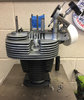
It turns out the head steady lug on a Gold Star couldn't be more a more perfect mounting location had BSA designed is specifically for this purpose. The Bosch knock sensor and aftermarket control unit I installed actually works. Adjusted as per instructions the LED flashed only infrequently with what I assume were false positives, but when I headed up a hill with the Catalina going way too slow in 4th I got the engine to rattle momentarily even with the 100 octane I had in the tank, and at the same time the LED flashed vigorously. The LED is quite bright even in the fullness of the almost-noon July desert sun.How do you plan on attaching your knock sensor?
When the 100 octane fuel was used up I filled it with 91 octane. I thought the knock sensor wasn't working because I didn't see it flash on the 2 miles out of the neighborhood. But, when I did an acceleration run I thought I might be hearing pinging, and when I looked down the knock light was flashing. Retarding the spark at that point turned off the light (and reduced the acceleration). So, even 8:1 has issues with the highest octane available at the pump. At least, there are issues when doing an uphill acceleration run starting at the low end of 4th gear speeds. By the way, if I hadn't had the knock sensor to consult, the faint sound of the pinging over the noise from the engine and wind might not have entered my consciousness
I must not have mentioned all the time I spent on the flow bench this spring. See below.Once you finish exploring your rabbit hole, you should ( must?) follow the branch that leads over to the other side. You could have some fun playing around with intake runner length and velocity stacks?
Don't think this hasn't crossed my mind. Unfortunately, I don't think the neighbors would tolerate it. However, I've been doing the next-best thing.Been thinking that your lovely bride should just give up and cash in her 401k...buy you a dyno and not have to chase you around the desert in 100+ heat.
I assembled 35 Gold Star factory dyno curves covering all configurations (road, scrambles, Clubmans,...) of 350cc and 500cc machines from ZB through DBD. I've then been "calibrating" an engine simulation program by feeding it as much actual data as I can collect to eliminate as many variables as possible while fitting the measured curves. So, various combinations of heads, carburetors, velocity stacks, exhaust pipes, silencers, etc. found themselves attached to my flow bench over the past few months.
The idea behind doing this is that, once "calibrated" by fitting known curves, the program will let me "build" engines in the comfort of my office in any desired configuration (e.g. trials cams in a Clubman with a long intake runner) and then quietly "measure" the resultant h.p. and torque vs. rpm. It was fairly smooth sailing until Microsoft threw a roadblock in my way three weeks ago when it did an automatic Windows update that failed to fully install, causing my office computer not to recognize the printer. Having paper copies is essential to my dyno workflow so this halted progress. I'm pretty good with such things but nothing I tried worked. Luckily, what Microsoft tooketh, Microsoft gaveth back three weeks later with a subsequent update.
As the above shows, a foolish person can find himself down multiple rabbit holes simultaneously.
Attachments
Yes neighbors.... I have difficulty taking the high road when it comes to that. Probably has something to do with the guy next door with the Harley straight pipes and all the yapping dogs surrounding me. I’m sure I’ve mentioned before that I’m looking forward to my next motorcycle project that will even the score.
You’d be the coolest kid on the block and you know you want one. I’m sure someone with your reasoning powers could get the bride to pay for it. After all... (speaking from experience) she is your human credential in that department... yes/ no?
Knock sensor is slick and results are interesting. I could use one of those to change ignition maps instead of or in addition to a VOS.
PS... I don’t have any Innovate stuff, so NMRH!
While I concede that those RamAir carburettor intakes May improve power, don’t they have an adverse effect on cornering speed?
We live ~1 mile up a quiet street that dead-ends a little further along, and I've never seen another motorcycle in the neighborhood, so around here I am that neighbor.Yes neighbors....