Comet suspension

Howard

Well Known and Active Forum User
VOC Member
Hi Rob (or Bro as I'll probably read it) I love these long technical discussions, I tend to look at them from a slightly different angle. I'm not an Auto Engineer but I use a lot of the same components designing industrial mechanical power transmission systems, so it's a bit like work without the work.

If you want adjustable preload, why not use an eyebolt system like the damper? You could adjust the ride height and preload by turning the inner spring cover to compress the spring without removing the spring box. Wind it up if you want to carry heavy loads, or down to remove the springs safely. Am I missing something (as usual)?

H
 

hadronuk

Well Known and Active Forum User
VOC Member
Hi Rob (or Bro as I'll probably read it) I love these long technical discussions, I tend to look at them from a slightly different angle. I'm not an Auto Engineer but I use a lot of the same components designing industrial mechanical power transmission systems, so it's a bit like work without the work.

If you want adjustable preload, why not use an eyebolt system like the damper? You could adjust the ride height and preload by turning the inner spring cover to compress the spring without removing the spring box. Wind it up if you want to carry heavy loads, or down to remove the springs safely. Am I missing something (as usual)?

H
Hi Howard, That would work, especially if you were the manufacturer, but for a one-off a bit of a problem is that the tubes are (I am told) a non-standard size, so you would probably have to modify an expensive original component. My degressive spring system, once assembled, is short enough to not require a spring compressor when fitting to the bike, so is much quicker to change anyway. Thanks for the comment, it has given me an idea! Rob.
 
Last edited:

hadronuk

Well Known and Active Forum User
VOC Member
Is this the sort of steep damper angle you are referring to?

Wow! That's well cranked over for a road bike. Great to see a Vincent being used enthusiastically, I shows everyone they are not just collectors items for static display and slow parades.
 
Last edited:

greg brillus

Well Known and Active Forum User
VOC Member
Hi Rob, Greg here....yes it's a great photo. I've had my Rapide out at one of the local short circut tracks here in Australia a few times and pretty much ground the rubbers down to the metal ( good thing they fold up..!!) and mine is a normal road bike. Sorry about not answering you earlier about the springs from your post yesterday, i didn't look to the bit bellow your photo.....Anyway, what i ment by the shorter springs being softer was, by comparison with the original dual springs that were there originally...I am fairly light weight and found the front end way too stiff.....so i removed the inner springs and found it much better. Then after speaking with davidd some time ago, i bought some sets of springs off of Sam Manganaro and fitted the blue ones which are for a standard twin. After which i have found that the suspension is probably a bit stiffer than with the original outers, but the trade off is the safer possition of the links....I suppose i could try one of the red springs ( for the singles) in one springbox and that may soften it up more, but i am happy with it as it is for now.....really enjoying yours and others posts into this very important subject too, I might add.........Greg.
 

John Emanuel

Active Forum User
Non-VOC Member
After I'd ridden my Rapide for around 15000 miles in the 1960's I had a tank slapper. When I rebuilt the bike in the late 1980's, I tried to find a reason for this extremely rare but potentially lethal phenomenun. It struck me that the path of the front wheel going up and forward rather than up and back was a possible contributing factor I therefore made a steering column tube which positions the bottom link eccentric position, lower and further back than standard. The result is that the wheel now moves up and back. The forks no longer lift under braking and the front end absorbs bumps far better than the standard set up.
I would like to send some photos but I'm not clever enough!!.....I'll happily Email them if anyone's interested....I've just about mastered that!
 

Howard

Well Known and Active Forum User
VOC Member
After I'd ridden my Rapide for around 15000 miles in the 1960's I had a tank slapper. When I rebuilt the bike in the late 1980's, I tried to find a reason for this extremely rare but potentially lethal phenomenun. It struck me that the path of the front wheel going up and forward rather than up and back was a possible contributing factor I therefore made a steering column tube which positions the bottom link eccentric position, lower and further back than standard. The result is that the wheel now moves up and back. The forks no longer lift under braking and the front end absorbs bumps far better than the standard set up.
I would like to send some photos but I'm not clever enough!!.....I'll happily Email them if anyone's interested....I've just about mastered that!

Hi John, glad you've got round to this, I was impressed with what you'd done at Curborough. email to me h.worrall2@ntlworld.com and I'll put them on the forum for you.

Regards

Howard
 

hadronuk

Well Known and Active Forum User
VOC Member
Spreadsheet model of Girdraulic axle path.

After I'd ridden my Rapide for around 15000 miles in the 1960's I had a tank slapper. When I rebuilt the bike in the late 1980's, I tried to find a reason for this extremely rare but potentially lethal phenomenun. It struck me that the path of the front wheel going up and forward rather than up and back was a possible contributing factor I therefore made a steering column tube which positions the bottom link eccentric position, lower and further back than standard. The result is that the wheel now moves up and back. The forks no longer lift under braking and the front end absorbs bumps far better than the standard set up.
I would like to send some photos but I'm not clever enough!!.....I'll happily Email them if anyone's interested....I've just about mastered that!

Hi John. I'd like to see the pictures. Do you have the dimensions? If so, and it is of interest, will try to model the geometry. As a first attempt at modelling other geometries, I have had a go at the John Renwick mod, which looks as if it has similar effects to what you describe. (I thought this would be the easiest to convert into my coordinate system, but I was wrong). As I understand it, this repositioned the bottom link 1 inch higher in the blades and 9/32 forward. I have compared it to a standard Girdraulic with the eccentrics replaced by a concentrics. It seems odd that the suspension travel is reduced, but I suppose this is because the wheel spindle now follows a circle of a smaller radius.

Standard Girdraulics in black, Renwick modded in green for 1/2 inch higher and red for 1 inch higher. The scale dimensions are in inches from my chosen reference points, so are a bit arbitrary.

Many thanks to David Dunfey for providing a copy of his calculations to test my model against, it has been invaluable.
Renwickpathwithconcentrics2_zps3035d700.jpg
 
Last edited:

Howard

Well Known and Active Forum User
VOC Member
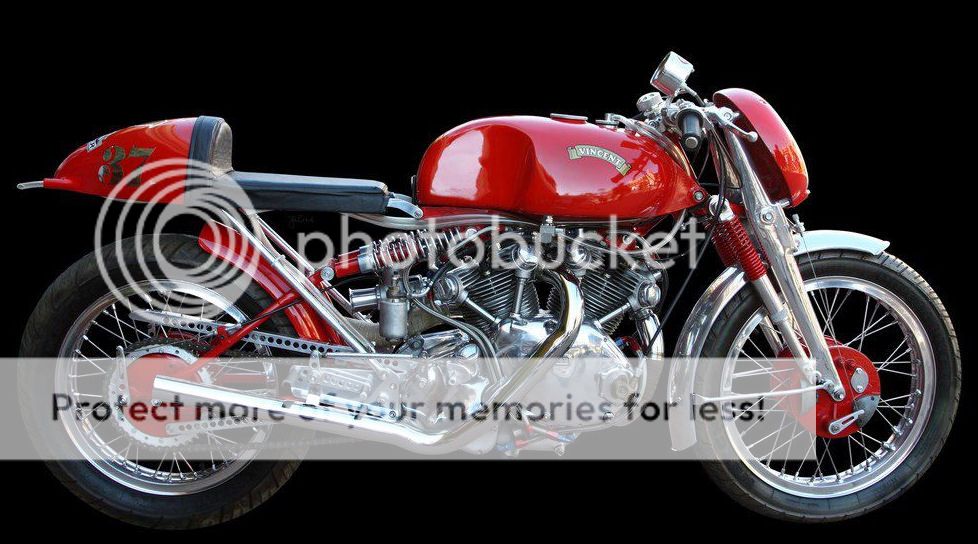
If those are Girlings on the back, it must have about 6" rear wheel movement, but the front looks as though it will be coil bound with a rider on board. Someone's put a lot of effort into that, be nice to know more about it.

H
 
Top